Base station antenna and high-frequency radiation unit thereof

A radiating unit and high-frequency technology, which is applied to antenna unit combinations with different polarization directions, radiating element structure forms, antennas, etc., can solve problems such as increasing high and low frequency radiating units, degrading low-frequency signal performance, and increasing antenna manufacturing costs , to achieve the effects of reducing parasitic radiation, simplifying the structure, and reducing solder joints

Pending Publication Date: 2021-11-26
COMBA TELECOM TECH (GUANGZHOU) CO LTD
View PDF0 Cites 0 Cited by
  • Summary
  • Abstract
  • Description
  • Claims
  • Application Information

AI Technical Summary

Problems solved by technology

[0003] However, in a multi-frequency antenna system, in order to meet the demand for miniaturization, the arrays of different frequency bands are arranged extremely compactly, resulting in mutual coupling
For example, a low-frequency radiation unit will generate a certain excitation signal to its adjacent high-frequency radiation unit, thereby generating spurious radiation, resulting in distortion of the pattern of the low-frequency signal, and a sharp decline in the performance of the low-frequency signal
To solve this problem, the existing solutions are generally to increase the distance between high and low frequency radiating units, or to design complex radiating units to achieve the decoupling function, which is not conducive to the miniaturization of the antenna, and will also improve the antenna manufacturing cost

Method used


Image

  • Base station antenna and high-frequency radiation unit thereof
  • Base station antenna and high-frequency radiation unit thereof
  • Base station antenna and high-frequency radiation unit thereof

Examples


Embodiment Construction

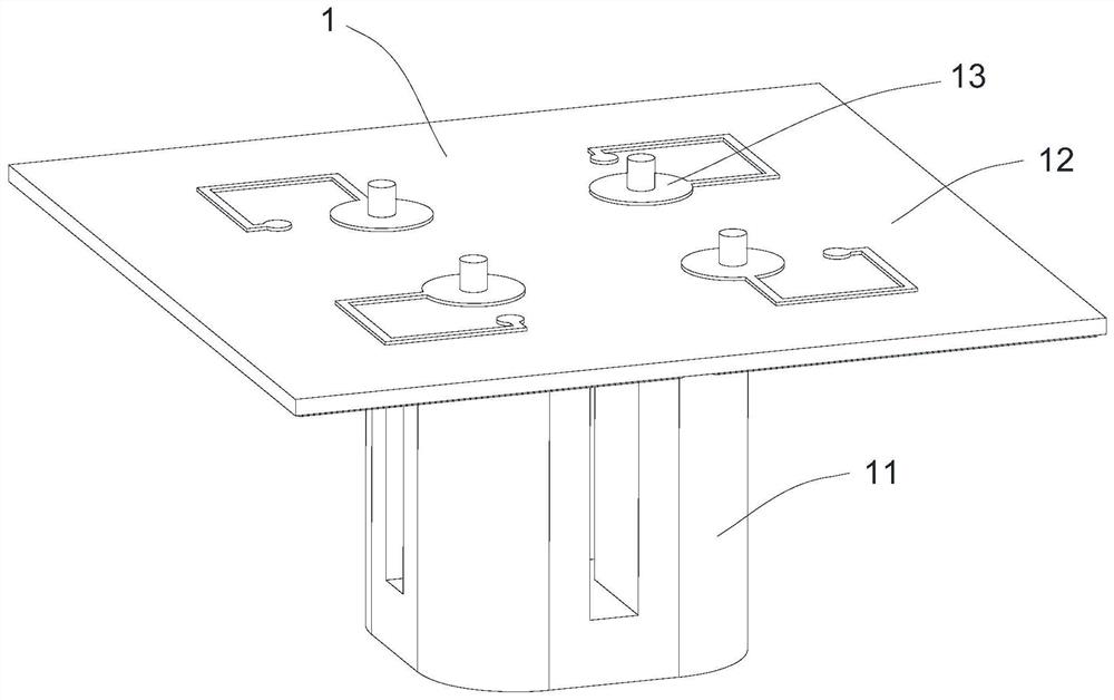
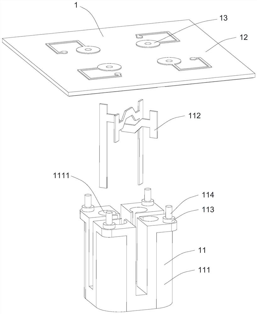
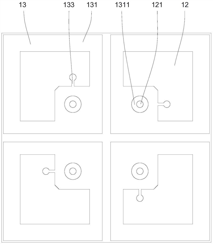
[0031] Embodiments of the present invention are described in detail below, examples of which are shown in the drawings, wherein the same or similar reference numerals designate the same or similar elements or elements having the same or similar functions throughout. The embodiments described below by referring to the figures are exemplary only for explaining the present invention and should not be construed as limiting the present invention.

[0032] Those skilled in the art can understand that, unless otherwise stated, the word "comprising" used in the description of the present invention refers to the presence of the features, integers, steps, operations, parts / components and / or components, but does not exclude the presence or Add one or more other features, integers, steps, operations, parts / parts, components and / or groups thereof. It should be understood that when we refer to a part / component as being "connected" to another part / component, it may be directly connected to t...


PUM


Abstract

The invention provides a base station antenna and a high-frequency radiation unit thereof. The high-frequency radiation unit comprises a feed balun, a dielectric substrate disposed at the top of the feed balun, and two pairs of polarized orthogonal radiators which can perform feeding by the feed balun. Each radiator comprises a radiation sheet and a decoupling circuit which is electrically connected with the radiation sheet and is used for reducing low-frequency parasitic radiation, wherein the radiation sheet and the decoupling circuit are respectively arranged on two opposite surfaces of the dielectric substrate. According to the high-frequency radiation unit provided by the invention, the decoupling circuit is arranged on the dielectric substrate, the coupling signal of a low-frequency radiation unit adjacent to the high-frequency radiation unit can be effectively suppressed through the decoupling circuit, and parasitic radiation is reduced, so that the distance between the high-frequency radiation unit and the low-frequency radiation unit can be reduced on the premise of ensuring good low-frequency electrical performance, and miniaturization of the antenna is realized. and the decoupling circuit and the radiation sheet are respectively arranged on the two opposite surfaces of the dielectric substrate, so that the structure is simple and compact, and the cost control is facilitated.

Description

technical field [0001] The invention relates to the technical field of mobile communication, in particular to a high-frequency radiation unit and a base station antenna using the high-frequency radiation unit. Background technique [0002] With the rapid development of mobile communication technology, in the current multi-network coexistence environment, the demand for the number of base station antennas has doubled, and problems such as difficult site selection and inconvenient installation of base station antennas have become increasingly apparent. In order to save site and antenna resources, multi-frequency and miniaturization have become the main development directions of base station antennas. [0003] However, in a multi-frequency antenna system, in order to meet the requirement of miniaturization, the arrays of different frequency bands are arranged extremely compactly, which leads to mutual coupling phenomenon. For example, a low-frequency radiation unit will genera...

Claims


Application Information

Patent Timeline
Patent Type & Authority Applications(China)
IPC IPC(8): H01Q1/24H01Q1/36H01Q1/38H01Q1/50H01Q1/52H01Q21/00H01Q21/24
CPCH01Q1/246H01Q1/36H01Q1/38H01Q1/50H01Q1/52H01Q21/00H01Q21/24H01Q1/24
Inventor 郑之伦贾飞飞刘亮余行阳
Owner COMBA TELECOM TECH (GUANGZHOU) CO LTD
Why Eureka
Try Eureka