Liquid discharge device, inspection device with liquid discharge device, and cell culture device with liquid discharge device
A liquid discharge and matrix technology, applied in fluid controllers, laboratory utensils, laboratory containers, etc., can solve the problem that the liquid discharge head cannot be thoroughly cleaned, and achieve the effect of waste loss.
- Summary
- Abstract
- Description
- Claims
- Application Information
AI Technical Summary
Problems solved by technology
Method used
Image

Examples
Embodiment approach 1
[0031]
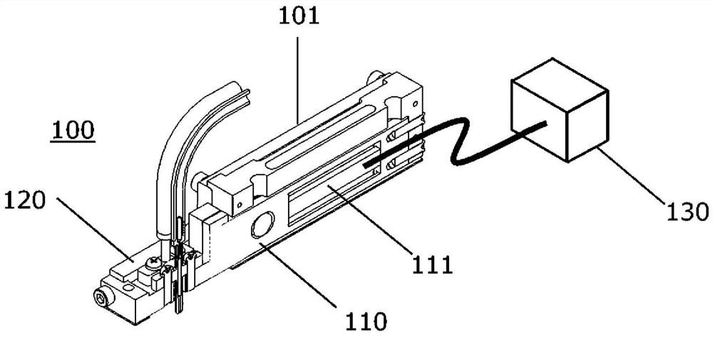
[0032] Figure 1A It is a schematic diagram showing the internal structure of the liquid discharge device according to Embodiment 1 of the present invention viewed obliquely. The inside of the base body 101 of the liquid discharge device 100 is equipped with a driving part 110 and a fixing part 120 . A piezoelectric element 111 that generates displacement is provided in the drive unit 110 , and the piezoelectric element 111 expands and contracts in synchronization with a drive pulse signal generated by an external waveform generator 130 to generate displacement.
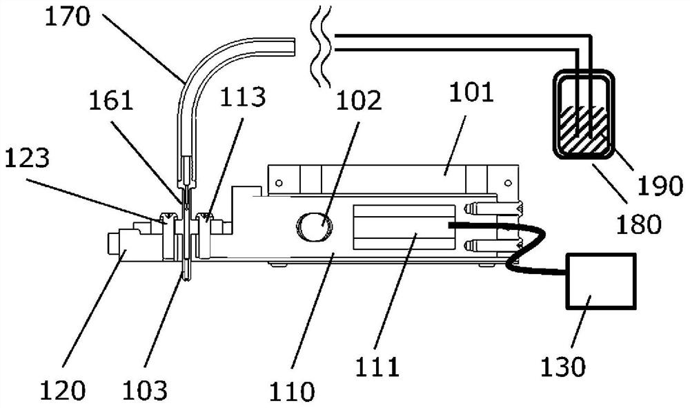
[0033] in addition, Figure 1B It is a schematic diagram showing the internal structure of the liquid discharge device 100 according to Embodiment 1 of the present invention viewed from the side. The driving part 110 is fixed behind the base 101 . In addition, the drive unit 110 is held using the fixing bar 102 to maintain the position of the drive unit 110 . The drive unit 110 into which the fixed rod ...
Embodiment approach 2
[0065]
[0066] Figure 5 It is a schematic diagram showing a cross-sectional structure of the liquid discharge device 200 in Embodiment 2 viewed from the side. Matters not described are the same as those of Embodiment 1. The difference from Embodiment 1 is that the nozzle is pressurized and compressed from both sides.
[0067] Inside the base body 201 of the liquid discharge device 200 are fitted a pair of driving parts 210 .
[0068] The drive unit 210 is equipped with a piezoelectric element 211 that generates displacement. These expand and contract in synchronization with the drive pulse signal generated by the external waveform generator 230 to generate displacement.
[0069] In addition, the drive unit 210 is fixed to the end of the base body 201 . In addition, in order to maintain the position of the drive part 210, it is held by the fixed rod 202. The drive unit 210 into which the fixing rod 202 is inserted is subjected to an oblong process whose major axis is t...
Embodiment approach 3
[0081] The liquid discharge devices 100 and 200 described above can apply a small amount of liquid with high precision and constant amount for a long time.
[0082] Therefore, it can be used for coating blood on biosensors, biochips, and the like. For example, when blood is applied to a blood sugar sensor, the liquid discharge device 100 or 200 is used to drip liquid onto the blood sugar sensor, and the blood sugar sensor is read by a detector to obtain a blood sugar level. With this method, the volume of blood is accurate and the result is correct.
[0083] It can also be coated on immune sensors such as tumor markers and heart disease markers instead of blood glucose level sensors. Furthermore, the sensor may be a DNA sensor for epigenetics, infectious diseases, or the like. As the sensor, a wide range of biosensors can be used.
[0084] use Figure 6A and Figure 6B A device according to Embodiment 3 will be described. Matters not described are the same as those of Em...
PUM
 Abstract
Description
Claims
Application Information
 - R&D
- Intellectual Property
- Life Sciences
- Materials
- Tech Scout
- Unparalleled Data Quality
- Higher Quality Content
- 60% Fewer Hallucinations
Browse by: Latest US Patents, China's latest patents, Technical Efficacy Thesaurus, Application Domain, Technology Topic, Popular Technical Reports.
© 2025 PatSnap. All rights reserved.Legal|Privacy policy|Modern Slavery Act Transparency Statement|Sitemap|About US| Contact US: help@patsnap.com