A DC Centralized Lighting System and a Method for Measuring the State of Its Lamps

A lighting system and measurement method technology, which is applied in the direction of lamp testing, measuring devices, lighting devices, etc., can solve problems such as unrealizable, complex networking, and inability to detect the status of a single lamp

Active Publication Date: 2021-03-19
DELTA ELECTRONICS (SHANGHAI) CO LTD
View PDF2 Cites 0 Cited by
  • Summary
  • Abstract
  • Description
  • Claims
  • Application Information

AI Technical Summary

Problems solved by technology

However, these two methods have certain defects. On the one hand, additional communication modules need to be added, the network is complex, easily disturbed, and the failure rate is also high; on the other hand, the cost of status detection is also high. Not suitable for some low-cost applications
[0005] In addition, the patent CN103763833B discloses a control method and system for controlling LED street lamps based on power supply lines. By adopting a DC power supply communication method, remote dimming and status detection of street lamps can be realized. However, this method can only control the lamp unit For overall control, unable to detect the status of individual lamps
Patent CN105101593B discloses a street lamp fault detection system and method, which uses the method of detecting the output current of the power cabinet to realize the fault detection of the lamp. However, this method can only realize the fault detection of the lamp during the process of turning off or turning on the lamp. And the form of lamp failure detection is single, only can know the on and off of a single lamp, can not detect other states of the lamp, such as energy consumption status, temperature status, etc.
[0006] When the state detection of a single lamp needs to be realized in any state, the above methods cannot be realized. Therefore, it is necessary to propose a DC centralized lighting system that can measure the state of the lamp and a measurement method for the state of the lamp to change the existing Negative effects of technology to solve problems in the current application process

Method used


Image

  • A DC Centralized Lighting System and a Method for Measuring the State of Its Lamps
  • A DC Centralized Lighting System and a Method for Measuring the State of Its Lamps
  • A DC Centralized Lighting System and a Method for Measuring the State of Its Lamps

Examples


Embodiment Construction

[0055] The technical solution of the present invention will be described in detail below in conjunction with illustrations and specific examples, so as to better understand the purpose, solution and effect of the present invention, but it is not intended as a limitation of the patent scope of the present invention.

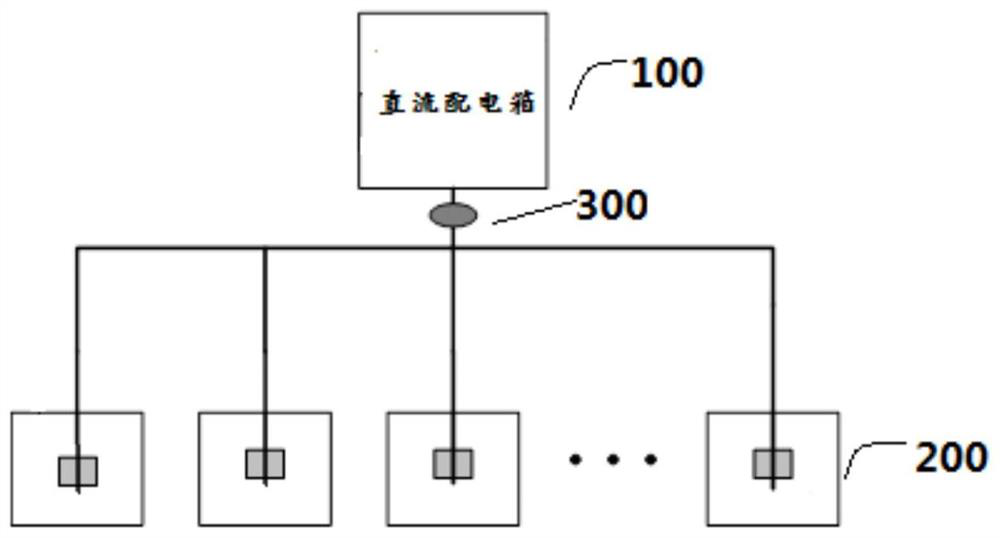
[0056] see image 3 and Figure 4 , image 3 It is a schematic diagram of a DC centralized lighting system using power lines for communication in the present invention, Figure 4 It is a schematic structural diagram of a lamp unit in an embodiment of the present invention. like image 3 and Figure 4 As shown, this embodiment discloses a DC centralized lighting system, including a DC distribution box 100, a plurality of lamp units 200, and a plurality of lamp units 200 are coupled in parallel to the DC distribution box 100, and each lamp unit 200 further It includes a lamp 2003 , a power conversion unit 2002 and an analog load unit 2001 .

[0057] The DC dis...


PUM


Abstract

The invention discloses a direct current centralized lighting system and a method for measuring the state of lamps and lanterns, wherein the system includes: a direct current distribution box and a plurality of lamp units, and the direct current distribution box converts the command protocol for controlling the state of the lamps into voltages with varying amplitudes The signal is output through a power line; each lamp unit includes a lamp, a power conversion unit and a simulated load unit, wherein the power conversion unit is coupled to the lamp and the simulated load unit, and is coupled to the DC distribution box through the power line; The conversion unit receives the voltage signal and judges whether the voltage signal matches the preset agreed rules; if the match is successful, the power conversion unit collects the status information of the lamp; and the power conversion unit controls the action of the simulated load unit to obtain the status information corresponding to the lamp. The current signal is transmitted back to the DC distribution box through the power line; the DC distribution box analyzes the current signal to obtain the status information of the lamp.

Description

technical field [0001] The invention relates to a direct current centralized lighting system, in particular to a direct current centralized lighting system capable of measuring the state of a lamp and a method for measuring the state of the lamp. Background technique [0002] In the DC centralized lighting system, it is very important for the DC distribution box to perform remote state detection of the lamps, such as the switch status of the lamps, the state of energy consumption and the detection of the working temperature state, etc., so as to know whether the lamps are faulty or working normally. [0003] During the use of the existing DC centralized lighting system, it is inevitable that there will be faulty lamps. At present, the location and judgment of faulty lamps are mostly determined manually. This method is often only dealt with when the lamps are damaged. In time, it brings a lot of inconvenience to the later maintenance of the project, and also causes troubles t...

Claims


Application Information

Patent Timeline
Patent Type & Authority Patents(China)
IPC IPC(8): G01R31/44H05B44/00
CPCG01R31/44H05B47/175H05B47/10H02J1/082H05B45/37H05B45/395H02J13/00002G01R15/202G01R19/0092
Inventor 杨波张涛石晓菁夏孝军
Owner DELTA ELECTRONICS (SHANGHAI) CO LTD
Why Eureka
Try Eureka