Improved structure for dispensing machine

A dispensing machine, an improved technology, applied in the direction of the surface coating liquid device, coating, etc., can solve the problems of affecting production work, unsightly, and affecting

Inactive Publication Date: 2012-07-04
NANTONG BEICHENG SCI & TECH ENTREPRENEURIAL MANAGEMENT
View PDF5 Cites 2 Cited by
  • Summary
  • Abstract
  • Description
  • Claims
  • Application Information

AI Technical Summary

Problems solved by technology

The disadvantages of the current dispensing machines on the market are: First, the distance between the driving wheel and the driven wheel is fixed. When the belt is used for a long time, it will inevitably be looser than the beginning, which will affect the level of the machine head. The movement causes adverse effects, so the belt needs to be replaced regularly to ensure the stable and reliable operation of the equipment; second, the power connection between the machine head and the control mechanism of the dispenser passes through the machine head and is directly scattered outside, not only It is not beautiful, and there are potential safety hazards, and it will also affect the normal production work

Method used


Image

  • Improved structure for dispensing machine
  • Improved structure for dispensing machine
  • Improved structure for dispensing machine

Examples


Embodiment Construction

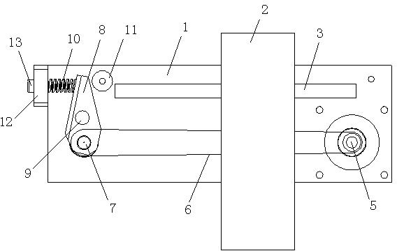
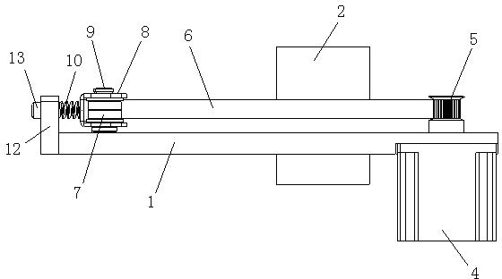
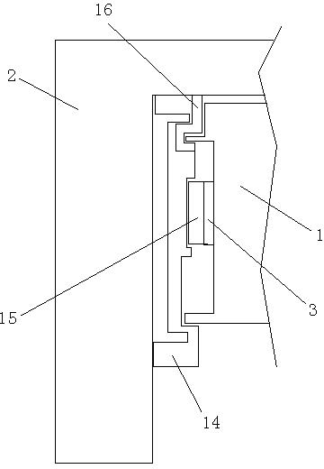
[0019] In this example, refer to figure 1 , figure 2 and image 3 , the improved structure of the dispenser includes a fuselage and a dispenser head 2, a crossbeam 1 is arranged on the fuselage, and the head 2 is installed on the crossbeam 1, and the crossbeam 1 is provided with a motor 4, a driving wheel 5, Belt 6, driven wheel 7 and slide rail 3, motor 4 connects driving wheel 5, and belt 6 is installed on driving wheel 5 and driven wheel 7; Slider 15, machine head 2 is located on the slide rail 3 by slider 15; An adjustment block 8 is installed on the beam 1, and the adjustment block 8 is installed on the beam 1 in a rotatable manner through a rotating shaft 9, and the adjustment block 8 and The driven wheel 7 is aligned, and the driven wheel 7 is installed on the lower end of the adjustment block 8 , and a spring 10 is connected to the outer surface of the upper end of the adjustment block 8 , and the other end of the spring 10 is fixed on the crossbeam 1 .

[0020] Th...


PUM


Abstract

The invention discloses an improved structure for a dispensing machine. The improved structure comprises a machine body and a dispensing handpiece, wherein a cross beam is arranged on the machine body; the handpiece is arranged on the cross beam; a motor, a driving wheel, a belt, a driven wheel and a sliding rail are arranged on the cross beam; a handpiece mounting plate is arranged on the handpiece; an adjustment block is arranged on the cross beam through a rotating shaft; the driven wheel is arranged at the lower end of the adjustment block; a spring is connected to the outer side face of the upper end of the adjustment block and fixed on the cross beam; and a power line mounting slot is formed on the side face of the upper end of the handpiece mounting plate. A position adjustment block is arranged at the position of the driven wheel; when the belt looses, the adjustment block can be used for automatically adjusting a distance between the driven wheel and the driving wheel under the action of the spring, so that the original tightness of the belt is guaranteed, and equipment can work normally; and furthermore, all power connection lines between the handpiece and a control mechanism are arranged in the power line mounting slot of the handpiece mounting plate, so that the dispensing machine is attractive and relatively safe.

Description

[0001] technical field [0002] The invention relates to the technical field of glue dispenser equipment, in particular to a head mounting structure of a glue dispenser. [0003] Background technique [0004] Dispensing machine is a very widely used industrial production equipment. Its structure is usually a beam on the fuselage, and a dispensing head is installed on the beam. The dispensing head is driven by a motor, a transmission wheel and a belt to move horizontally. The dispensing head is equipped with an up and down moving device. The disadvantages of the current dispensing machines on the market are: First, the distance between the driving wheel and the driven wheel is fixed. When the belt is used for a long time, it will inevitably be looser than the beginning, which will affect the level of the machine head. The movement causes adverse effects, so the belt needs to be replaced regularly to ensure the stable and reliable operation of the equipment; second, the powe...

Claims


Application Information

Patent Timeline
Patent Type & Authority Applications(China)
IPC IPC(8): B05C5/00B05C11/00
Inventor 夏勇
Owner NANTONG BEICHENG SCI & TECH ENTREPRENEURIAL MANAGEMENT
Why Eureka
Try Eureka