Pressure-measuring glow plug

a technology of pressure measurement and glow plugs, which is applied in the direction of lighting and heating apparatus, instruments, machines/engines, etc., can solve problems such as component loading, and achieve the effect of small spring rate and ensuring the required pressure loading

Active Publication Date: 2007-06-12
SENSATA TECH HOLLAND +1
View PDF15 Cites 30 Cited by
  • Summary
  • Abstract
  • Description
  • Claims
  • Application Information

AI Technical Summary

Benefits of technology

[0008]A bellows-like seal has the advantage that absolute tightness of the pressure-measuring glow plug is guaranteed in the region between heating rod and the plug body with respect to be prevailing combustion pressure.
[0010]As a result of the multi-layer structure of the bellows-like component, a small spring rate and the required pressure loading can be guaranteed.
[0011]A further advantage is that influences on the pressure sensor as a result of thermal loading during the glow operation or with different engine load states are minimal.

Problems solved by technology

Use of metal membrane as a seal, however, has the drawback of a stiff spring characteristic and a small spring excursion, which leads to component loading.

Method used


Image

  • Pressure-measuring glow plug
  • Pressure-measuring glow plug
  • Pressure-measuring glow plug

Examples


Embodiment Construction

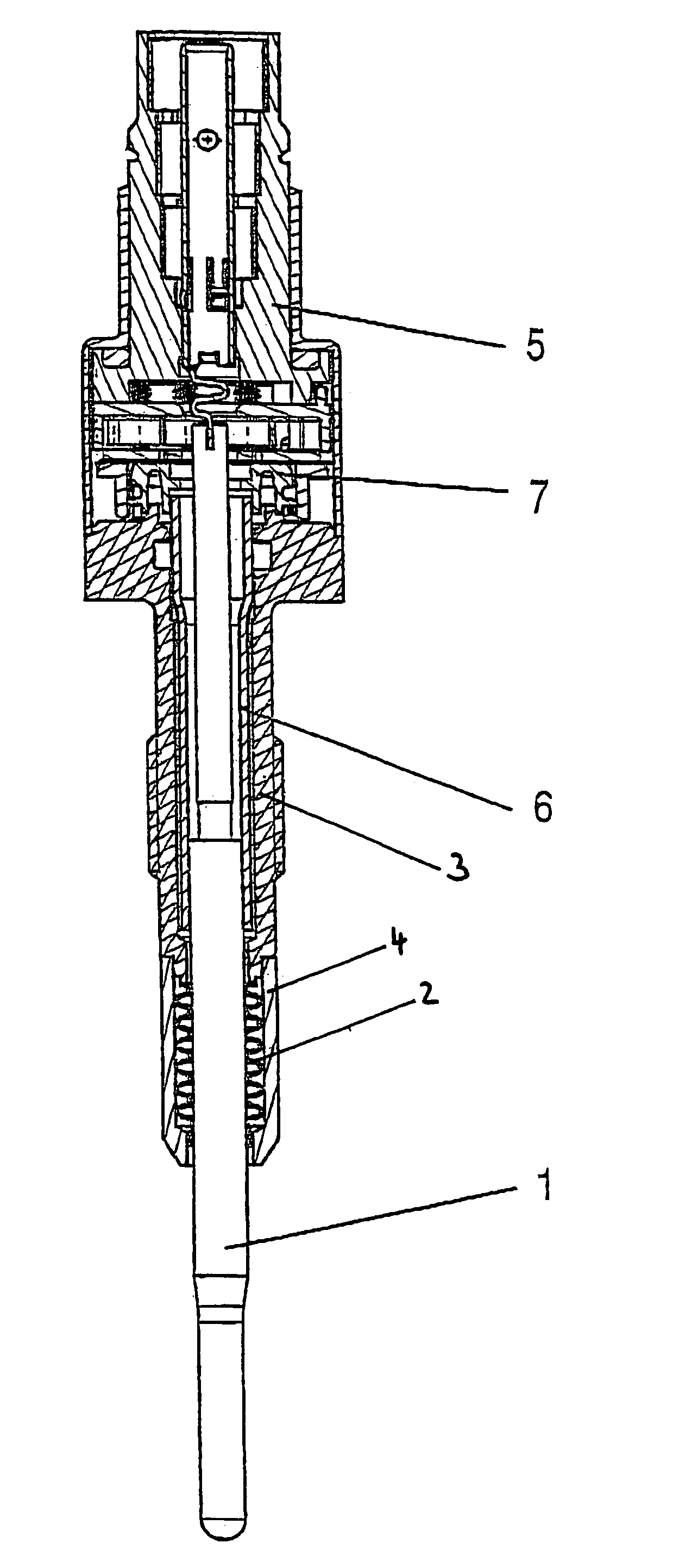
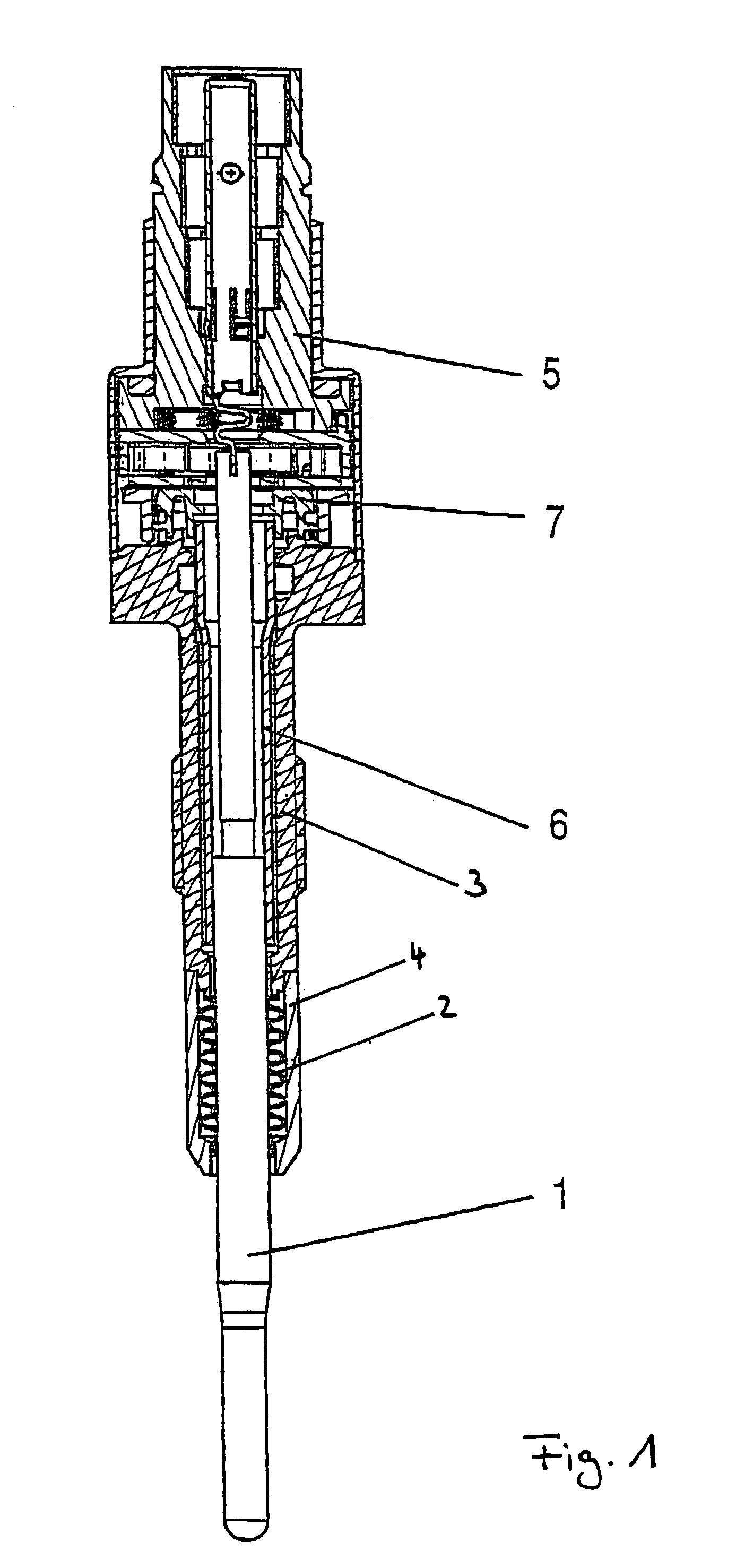
[0015]As is shown in FIG. 1, a pressure-measuring glow plug for a diesel engine essentially comprises a plug body 3, 4, a heating rod 1 with a metallic or ceramic structure, which is arranged in the glow plug so as to be displaceable in a sliding manner in the axial direction relative to plug body 3, 4, a pressure sensor 7, which is arranged between heating rod 1 and plug body 3, 4, optionally, under an initial tension by means of a sensor unit 5 and is acted on by the pressure prevailing in the combustion chamber of the cylinder, whereby heating rod 1 transmits the pressure in the combustion chamber of the cylinder to pressure sensor 7.

[0016]Heating rod 1 is arranged so as to be displaceable in a sliding manner in the axial direction relative to plug body 3, 4, in such a way that the pressure in the combustion chamber leads to an axial motion of heating rod 1 relative to plug body 3, 4, and as a result of this axial motion, a force acts on pressure sensor 7.

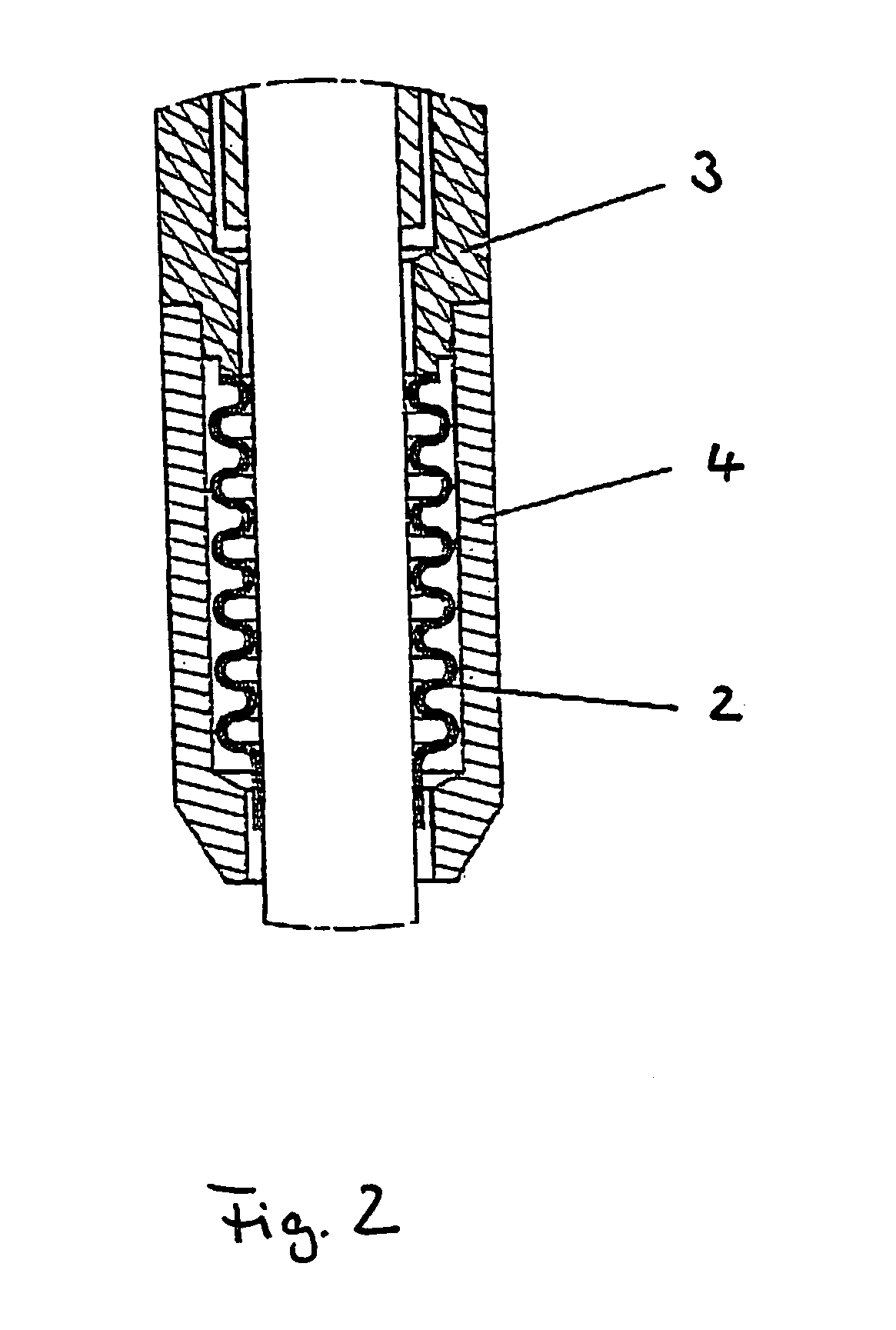
[0017]As is shown in FIG...


PUM


Abstract

A pressure-measuring glow plug for a diesel engine with a plug body (3, 4) for insertion into a cylinder of the diesel engine, a heating rod (1) which is arranged in the plug body (3, 4), and a pressure sensor, which is arranged under an initial tension between the heating rod (1) and the plug body (3, 4), in such a way that the pressure sensor (7) is acted upon by the pressure prevailing in the combustion chamber of the cylinder. The heating rod (1) transmits the pressure in the combustion chamber of the cylinder to the pressure sensor (7) and is arranged so as to be displaceable in a sliding manner in the axial direction relative to the plug body (3, 4). A seal in the form of a bellows-shaped component (2) is provided between the heating rod (1) and the plug body (3, 4).

Description

BACKGROUND OF THE INVENTION[0001]1. Field of Invention[0002]The invention relates to a pressure-measuring glow plug for a diesel engine with a plug body for insertion into a cylinder of the diesel engine, a heating rod which is arranged in the plug body, and a pressure sensor, which is arranged under an initial tension between the heating rod and the plug body in such a way that the pressure sensor is acted upon by the pressure prevailing in the combustion chamber of the cylinder, whereby the heating rod transmits the pressure in the combustion chamber of the cylinder to the pressure sensor and in which the heating rod is arranged in the plug body so as to be displaceable in a sliding manner in the axial direction relative to the plug body, so that the pressure in the combustion chamber leads to an axial motion of the heating rod relative to the plug body, as a result of which motion the pressure sensor is acted upon by a force.[0003]2. Description of Related Art[0004]With a pressur...

Claims


Application Information

Patent Timeline
Patent Type & Authority Patents(United States)
IPC IPC(8): G01M15/00
CPCF23Q7/001F02P19/028F23Q2007/002F23Q7/00F23Q7/22
Inventor HAUSSNER, MICHAELHOUBEN, HANSPECHHOLD, FRANKMAYR, FRIEDRICHWYRWICH, ULF
Owner SENSATA TECH HOLLAND
Why Eureka
Try Eureka