
A method of bilateral power supply for electrified railway
A technology for electrified railways, power supply methods, applied in the direction of power lines, vehicle components, transportation and packaging, etc., to achieve the effects of avoiding adverse effects, easy implementation, and optimized capacity
- Summary
- Abstract
- Description
- Claims
- Application Information
AI Technical Summary
Problems solved by technology
Method used
Image

Examples
Embodiment Construction
[0022] In order to better understand the present invention, the present invention will be further described below in conjunction with the accompanying drawings and specific embodiments.
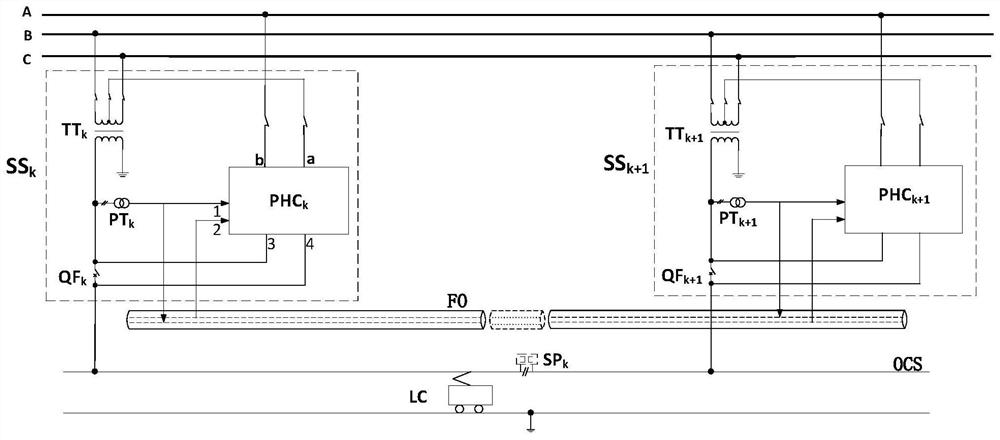
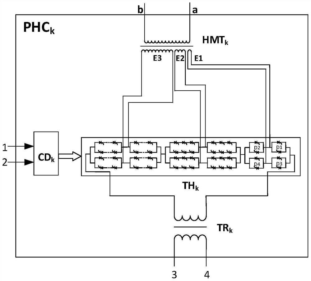
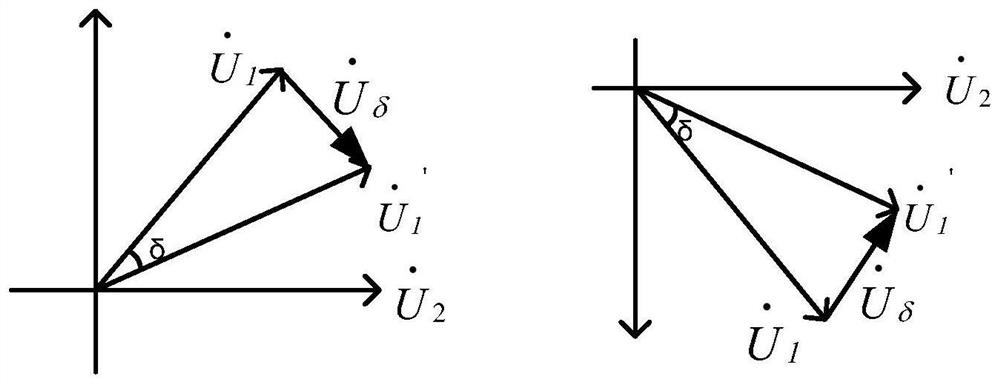
[0023] A bilateral power supply method for electrified railways, including traction substation SS k and adjacent traction substation SS k+1 And the traction network OCS, subdivision SP k ; The traction substation SS k Built-in traction transformer TT k , voltage compensation device PHC k ; The voltage compensation device PHC k Including High Voltage Shunt Transformer HMT k , thyristor valve group TH k , controller CD k , traction series transformer TR k ; Wherein, the traction transformer TT k , voltage compensation device PHC k Both are single-phase structure, high-voltage shunt transformer HMT k One end a of the primary winding and the traction transformer TT k The midpoint of the primary winding is connected; the traction transformer TT k The primary winding is connected to th...
PUM
 Abstract
Description
Claims
Application Information