
Knob switch and intelligent automobile
A knob switch, knob technology, applied in electrical switches, electrical components, circuits, etc., can solve the problems of complex calculation logic, unstable resistance value, poor user experience, etc., to achieve simple calculation logic, avoid resistance changes, and increase users. The effect of experience
- Summary
- Abstract
- Description
- Claims
- Application Information
AI Technical Summary
Problems solved by technology
Method used
Image


Examples
Embodiment Construction
[0022] The following will clearly and completely describe the technical solutions in the embodiments of the present invention with reference to the accompanying drawings in the embodiments of the present invention. Obviously, the described embodiments are only some, not all, embodiments of the present invention. Based on the embodiments of the present invention, all other embodiments obtained by persons of ordinary skill in the art without making creative efforts belong to the protection scope of the present invention.
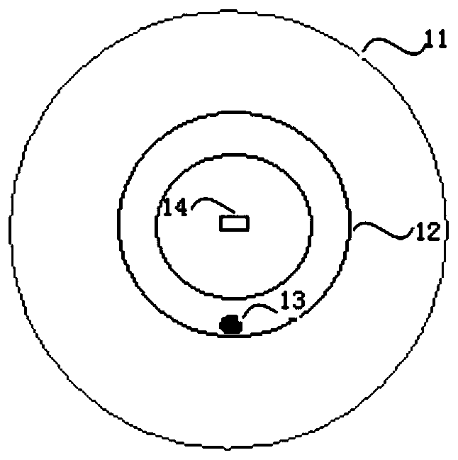
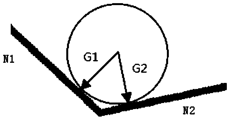
[0023] See figure 1 , figure 1 A structural diagram of a rotary switch provided by the embodiment of the present invention, the rotary switch includes: a rotary knob body 11, a closed cavity 12 is arranged on the rotary knob body 11, a ball 13 is arranged in the closed cavity 12, and the closed cavity 12 The inner wall is laid with a subsensitive resistor used for sensing the gravity change value of the sphere 13 during the rotation of the knob body 11. The k...
PUM
 Abstract
Description
Claims
Application Information