
Knife switch-type waterproof connector
A waterproof connector and knife technology, applied in the direction of connection, connecting device parts, electrical components, etc., can solve the problems of very high requirements, reducing the waterproof effect of the connector, elastic fatigue, etc.
- Summary
- Abstract
- Description
- Claims
- Application Information
AI Technical Summary
Problems solved by technology
Method used
Image

Examples
specific Embodiment approach
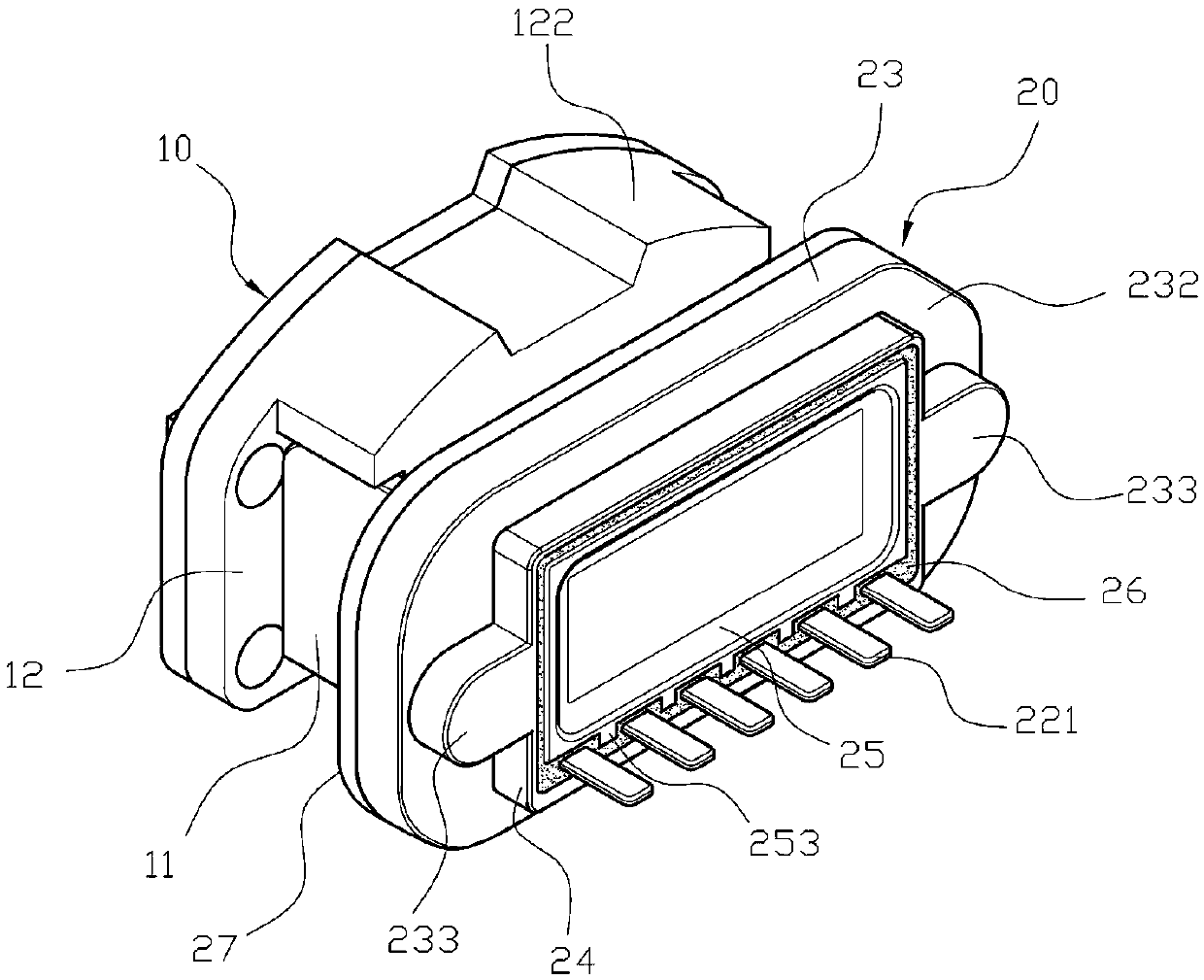
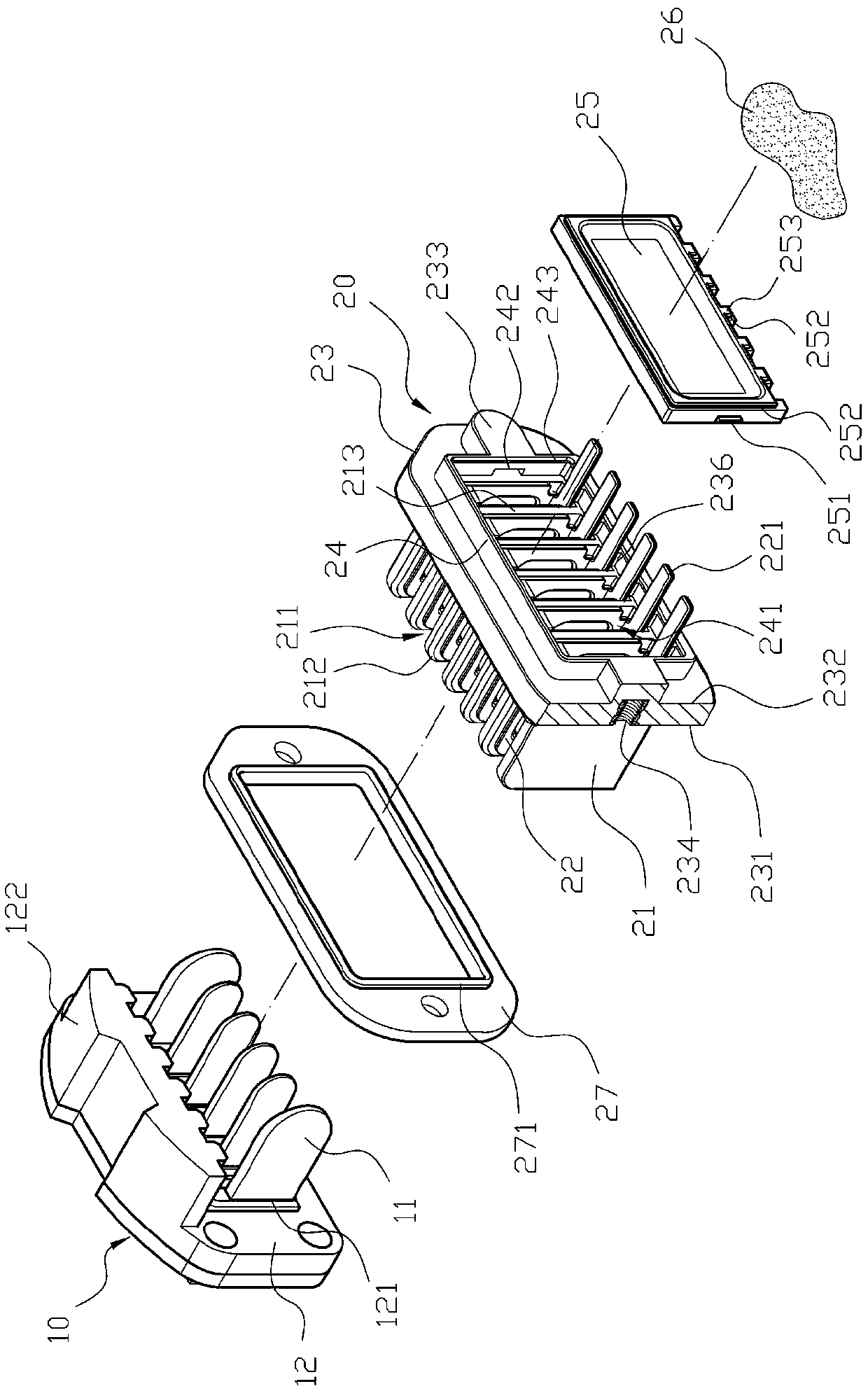
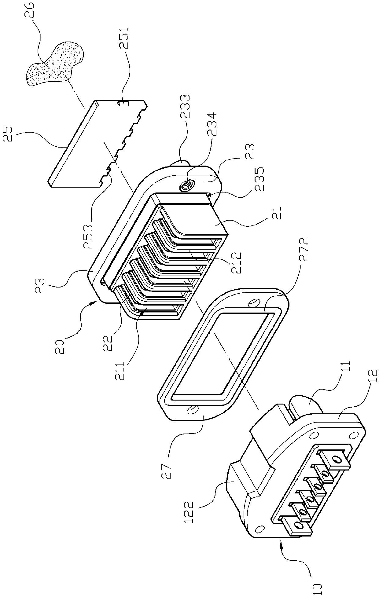
[0069] first please figure 1 Continuous to Figure 4 As shown, a knife-type waterproof connector includes: a first connector 10 and a second connector 20, a first connector 10 is provided with a plurality of first terminals 11, the first The connector 10 is combined with a seal 12, and the seal 12 is provided with a plurality of perforations 121, and the perforations 121 provide the penetration of the first terminal 11, and the seal 12 is right-angled, and the seal 12 A side block 122 is formed, and a second connecting member 20 forms a connecting seat 21 at one end, and the connecting seat 21 is in a right-angle shape, and the connecting seat 21 is provided with a plurality of L-shaped grooves 211, and each of the L-shaped grooves 211 A second terminal 22 is fixed inside, so that the first terminal 11 and the second terminal 22 are interconnected to form electrical conduction between the first connector 10 and the second connector 20, and the first terminal 11 When intercon...
PUM
 Abstract
Description
Claims
Application Information