An energy-saving CNC machine tool

A CNC machine tool, energy-saving technology, applied in metal processing machinery parts, manufacturing tools, drive devices, etc., can solve the problems of reducing production efficiency, complex transmission structure design, increasing processes, etc., to reduce energy consumption and ensure deburring effect. , the effect of reducing processing costs

A CNC machine tool, energy-saving technology, applied in metal processing machinery parts, manufacturing tools, drive devices, etc., can solve the problems of reducing production efficiency, complex transmission structure design, increasing processes, etc., to reduce energy consumption and ensure deburring effect. , the effect of reducing processing costs

CN110814439BInactive Publication Date: 2020-11-10常亮

Image

  • An energy-saving CNC machine tool
  • An energy-saving CNC machine tool
  • An energy-saving CNC machine tool

Examples


Embodiment Construction

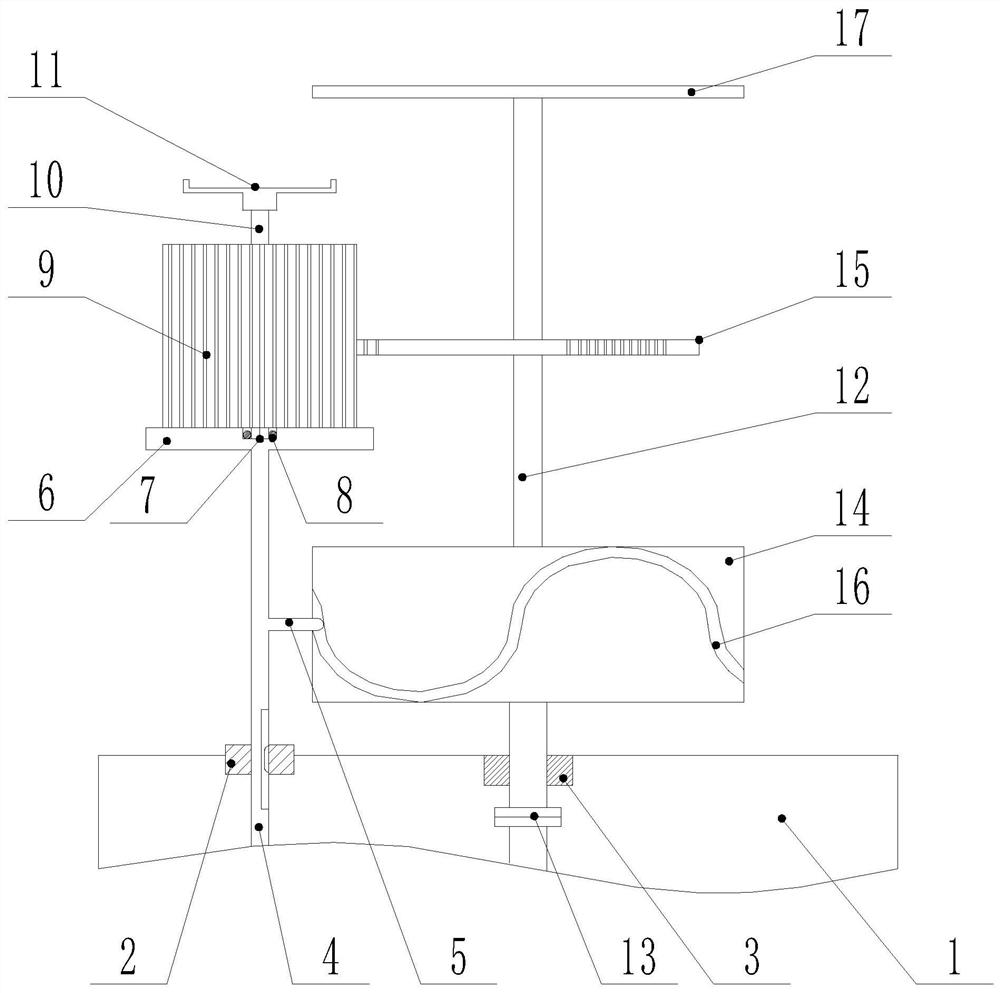
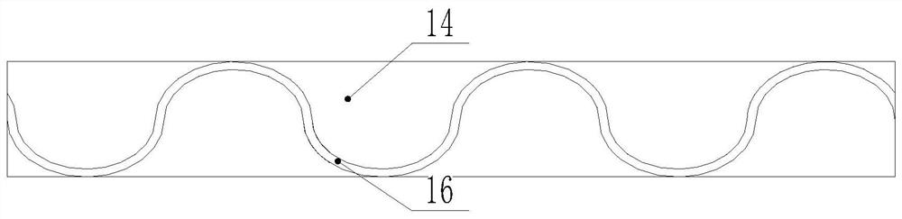
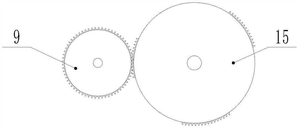
[0023] The present invention is specifically described below in conjunction with accompanying drawing, as Figure 1-4 As shown, the inventive point of the present application is that the lifting rod 4 is inserted into the shaft sleeve, and the lifting rod is inserted into the shaft sleeve through key fit, the lifting rod moves up and down relative to the shaft sleeve, and the lifting rod 4 moves up and down relative to the shaft sleeve. There is no relative rotation between the rod and the bushing, the side of the elevating rod is provided with a driving rod 5, the top of the elevating rod is fixedly mounted with a bearing plate 6, and the center of the upper surface of the bearing plate is provided with a groove 7. The gear 9 is movable on the plate, and the lower end of the central shaft 10 of the gear is inserted into the groove, and the workpiece bearing plate 11 is installed on the upper end of the central shaft; the driving shaft 12 is inserted on the bearing, and the low...


PUM


Abstract

The invention discloses an energy-saving numerical control machine tool convenient to use. The energy-saving numerical control machine tool includes a machine tool base, an axle sleeve and a bearing are arranged on the upper surface of the machine tool base, a motor is fixedly installed in the machine tool base, a lifting rod is inserted in the axle sleeve, the lifting rod is inserted in the axlesleeve by means of key matching, the lifting rod moves up and down relative to the axle sleeve, a shifting rod is arranged on the side face of the lifting rod, a bearing plate is fixedly installed atthe top end of the lifting rod, a groove is formed in the center of the upper surface of the bearing plate, a gear is movably installed on the bearing plate, the lower end of a central shaft of the gear is inserted into the groove, and a workpiece bearing and placing plate is installed at the upper end of the center shaft. The energy-saving numerical control machine tool has the beneficial effectsthat the structure is simple, and energy conservation and the practicality are achieved.

Description

technical field [0001] The invention relates to the field of numerical control machine tools, in particular to an energy-saving numerical control machine tool. Background technique [0002] In the process of mechanical processing, the workpiece is often processed by lathes, milling machines and planers. After the processing is completed, burrs will appear on the cutting surface of the workpiece. Usually, the burrs brought out by the cutting surface of the workpiece are manually polished. Remove burrs, but this method not only increases the process and reduces production efficiency, but also has high requirements for grinding technology, requiring staff to have certain work experience and skills; [0003] In order to solve the above problems, those skilled in the art have proposed to use the motor to drive the sheet cutter to cut off the burrs on the cutting surface of the workpiece, and to drive the sheet cutter close to the cutting surface of the workpiece through the manua...

Claims


Application Information

Patent Timeline
10 Nov 2020
Publication
CN110814439B
IPC
B23D79/02; B23Q5/04; B23Q5/32
CPC
B23D79/02; B23Q5/04; B23Q5/32
Inventors
常亮; 任传柱