Air convection type air dome building

An air film building and air convection technology, applied in the field of construction, can solve the problems of difficult assembly of ventilation equipment, complex structure of ventilation equipment, poor air convection, etc., and achieve significant technological progress, improve air quality, and increase bearing pressure. Effect

Active Publication Date: 2020-02-25
岳伟
View PDF5 Cites 0 Cited by
  • Summary
  • Abstract
  • Description
  • Claims
  • Application Information

AI Technical Summary

Problems solved by technology

[0002] The air film building is a new type of building with high technological content in the new era. This kind of building, its supporting mechanical units include inflatable parts, heating and cooling air conditioners, backup systems, etc.; the membrane material of this kind of building itself is light in weight, and it can realize a large-span clearance space without beams and columns, and the maximum span can reach 150 meters; at the same time The building has good flexibility, fast and convenient construction and disassembly, and environmentally friendly construction; at the same time, the building has excellent ventilation effects and outstanding safety. It is a new type of high-tech building; but the current air film buildings are mostly on the ground Set up an air supply and exhaust system. This air supply and exhaust system can only achieve air convection in the bottom space. For the higher positions of the air film building, the air convection is poor, and the air quality will also be discounted; due to the existing ventilation equipment The structure is complex and the weight is heavy. Due to the limitation of its own structure, it is difficult to assemble this kind of ventilation equipment on the upper part of the air film building; otherwise, there will be many problems such as support and safety.

Method used


Image

  • Air convection type air dome building
  • Air convection type air dome building
  • Air convection type air dome building

Examples


Embodiment

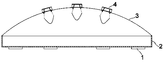
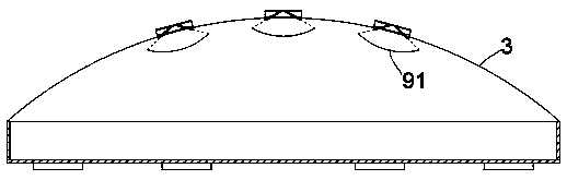
[0021] exist Figure 1 to Figure 3 In the shown embodiment, the air convection air film building includes an air supply and exhaust device 1, a fixed frame 2 and a membrane body 3; the air supply and exhaust device 1 is arranged on the ground of the building, and the fixed frame 2 forms a support frame, the membrane body 3 is wrapped and arranged on the supporting frame;

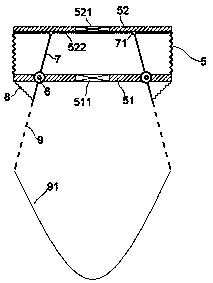
[0022] The membrane body 3 is provided with a convection unit 4; the convection unit 4 includes a telescopic cavity 5, and the bottom plate 51 of the telescopic cavity 5 is provided with an air intake valve 511 communicating with the inner chamber of the gas film building. The top plate 52 is provided with an exhaust valve 521 communicating with the outside air; the intake valve 511 and the exhaust valve 521 are electrically connected to a controller, and the controller alternately opens the intake valve 511 and the exhaust valve 521;

[0023] Fixed rotating shafts 6 are arranged on the bottom plate 51, and...


PUM


Abstract

The invention relates to an air convection type air dome building. The building comprises an air supply and exhaust device, a fixing frame and a dome body, wherein a convection unit is arranged on thedome body, the convection unit comprises a telescopic cavity, a bottom plate of the telescopic cavity is provided with an air inlet valve, and a top plate of the telescopic cavity is provided with anexhaust valve; fixed rotating shafts are arranged on the bottom plate, transmission plates are arranged on all the fixed rotating shafts in a sleeve mode, the transmission plates extend into the topedge of the telescopic cavity and is connected with the top plate, a slide fastener is installed at the top edge, a slide rail is mounted on the top plate, and the slide fastener is in sliding match with the slide rail; and the transmission plates extend out of a bottom edge of the telescopic cavity and are connected with a reset device, the length of the transmission plates extending into the telescopic cavity is larger than the length of the transmission plates extending out of the telescopic cavity, and a convection plate is further installed on the bottom edge. The air dome building is novel in structure and unique in principle, air circulation of high level can be effectively promoted, the air quality is improved, meanwhile, the decoration and light shadow effect can be effectively improved.

Description

technical field [0001] The invention relates to the field of buildings, in particular to an air film building. Background technique [0002] The air film building is a new type of building with high technological content in the new era. This kind of building, its supporting mechanical units include inflatable parts, heating and cooling air conditioners, backup systems, etc.; the membrane material of this kind of building itself is light in weight, and it can realize a large-span clearance space without beams and columns, and the maximum span can reach 150 meters; at the same time The building has good flexibility, fast and convenient construction and disassembly, and environmentally friendly construction; at the same time, the building has excellent ventilation effects and outstanding safety. It is a new type of high-tech building; but the current air film buildings are mostly on the ground Set up an air supply and exhaust system. This air supply and exhaust system can only...

Claims


Application Information

Patent Timeline
Patent Type & Authority Applications(China)
IPC IPC(8): E04B1/34F24F7/007F24F11/89
CPCE04B1/34F24F7/007F24F11/89Y02B30/70
Inventor 马人欢
Owner 岳伟
Why Eureka
Try Eureka