

Imaging lens
A camera lens, lens technology, applied in optical components, optics, instruments, etc., can solve problems such as disadvantage of miniaturization, and achieve the effect of ensuring internal space
- Summary
- Abstract
- Description
- Claims
- Application Information
AI Technical Summary
Problems solved by technology
Method used
Image

Examples
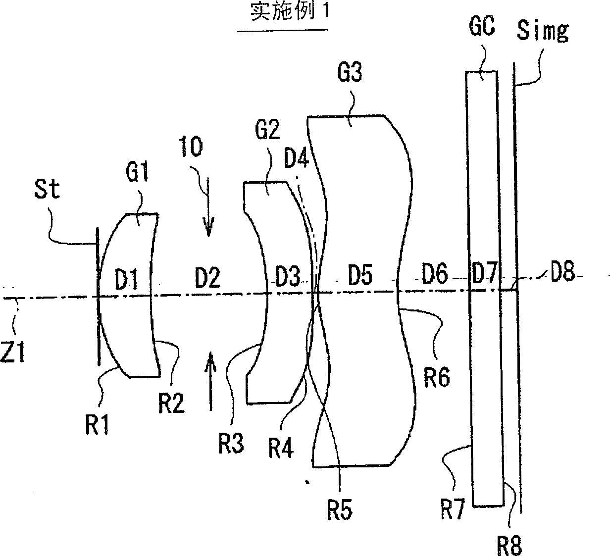
Embodiment 1
[0069] In the imaging lens according to Example 1, both surfaces of the first lens G1 , the second lens G2 , and the second lens G3 are aspherical. exist Figure 8 In the basic lens data of (A), the numerical value of the radius of curvature near the optical axis is shown as the radius of curvature of these aspherical surfaces. exist Figure 8 Among the numerical values shown as aspheric surface data in (B), the symbol "E" indicates that the data immediately following it is a "power exponent" with base 10, and indicates that it will be represented by the exponential function with base 10. The value is multiplied by the value preceding the "E". For example, if it is "1.0E-02", it means "1.0×10 -2 ".
[0070]As the aspheric surface data, the values of the respective coefficients An and K in the formula of the aspheric surface shape represented by the following formula (A) are shown. More specifically, Z represents the length (mm) of a perpendicular drawn from a point on...
PUM
 Abstract
Description
Claims
Application Information