Radar reflecting surface system and leveling method and building method thereof

A radar reflection and sub-reflection technology, used in radio wave measurement systems, measurement devices, instruments, etc., can solve the problems of large flatness error, difficult assembly, and difficult maintenance, and achieve the goal of reducing damage, low assembly difficulty, and easy maintenance. Effect

Active Publication Date: 2020-03-13
JIANGSU NANSHUI TECH +2
View PDF8 Cites 2 Cited by
  • Summary
  • Abstract
  • Description
  • Claims
  • Application Information

AI Technical Summary

Problems solved by technology

[0003] Since the radar reflective surface is usually large (for example, 2m*2m), in order to reduce the impact of the gap on the radar detection accuracy, users generally choose to use the whole board to make it, but the whole board making and assembly will inevitably lead to large flatness errors and difficult assembly. Difficult to maintain and other issues

Method used


Image

  • Radar reflecting surface system and leveling method and building method thereof
  • Radar reflecting surface system and leveling method and building method thereof
  • Radar reflecting surface system and leveling method and building method thereof

Examples


Embodiment Construction

[0050] In order to better understand the technical content of the present invention, specific embodiments are given together with the attached drawings for description as follows.

[0051] Aspects of the invention are described in this disclosure with reference to the accompanying drawings, which show a number of illustrated embodiments. Embodiments of the present disclosure are not necessarily defined to include all aspects of the present invention. It should be appreciated that the various concepts and embodiments described above, as well as those described in more detail below, can be implemented in any of numerous ways, since the concepts and embodiments disclosed herein are not limited to any implementation. In addition, some aspects of the present disclosure may be used alone or in any suitable combination with other aspects of the present disclosure.

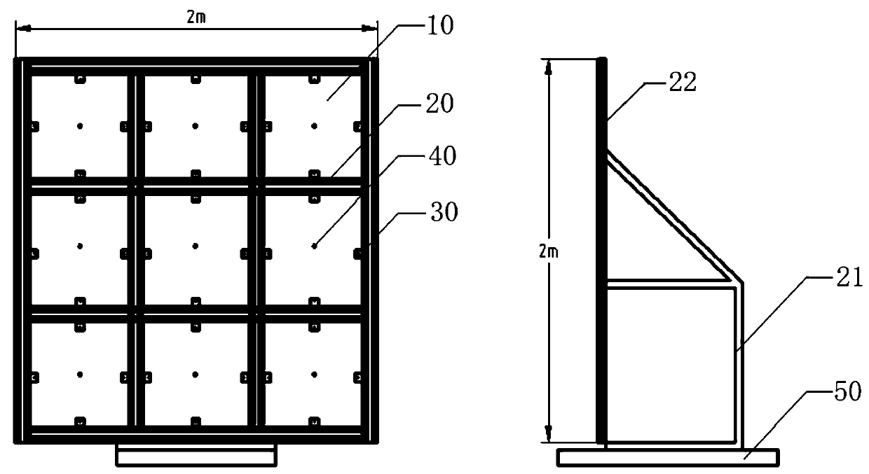
[0052] combine figure 1 , the present invention proposes a radar reflective surface system, the radar reflective sur...


PUM


Abstract

The invention provides a radar reflecting surface system and a leveling method and a building method thereof. A radar reflecting surface is manufactured by adopting a whole plate. The manufactured radar reflecting surface is installed on a supporting frame, and the radar reflecting surface is divided into a plurality of sub-reflecting surfaces by the supporting frame. A first adjustment point forcontrolling the edge area and a second adjustment point for controlling the center area are set for each sub-reflecting surface. The acting force borne by each adjustment point on each sub-reflectingsurface is comprehensively controlled in an iterative mode, and local flatness adjustment of the radar reflecting surface is realized. Finally, adjustment of the overall flatness of the radar reflection surface is completed.

Description

technical field [0001] The invention relates to the technical field of radar reflective surface production, in particular to a radar reflective surface system, a leveling method, and a building method thereof. Background technique [0002] As the application scenarios of radar become more and more extensive, the requirements for its measurement accuracy are also getting higher and higher. However, the current detection methods for radar equipment are quite limited. In order to achieve the accuracy of detection, it takes a lot of manpower and material resources to build a detection platform. The flatness control of the radar reflective surface is one of the most important installation joints, especially some users choose to build the radar detection platform by themselves, the flatness of the radar reflective surface is directly related to the detection accuracy of the radar equipment. [0003] Since the radar reflective surface is usually large (for example, 2m*2m), in order...

Claims


Application Information

Patent Timeline
IPC IPC(8): G01S7/40
CPCG01S7/4052G01S7/4082
Inventor 宗军姚刚曹子聪王坤邓超杨威陈杰中吴宁声李林兴张亚裘劲松唐培健陈玲魏广张逸飞刘伟
Owner JIANGSU NANSHUI TECH
Why Eureka
Try Eureka