Vehicle system transfer function solving method based on transfer matrix

A transfer matrix and transfer function technology, applied in the field of vehicle system transfer function solution, can solve problems such as error-prone and difficult, and achieve the effect of high degree of programmability and convenient calculation process.

Active Publication Date: 2020-03-13
CHANGCHUN INST OF OPTICS FINE MECHANICS & PHYSICS CHINESE ACAD OF SCI
View PDF13 Cites 2 Cited by
  • Summary
  • Abstract
  • Description
  • Claims
  • Application Information

AI Technical Summary

Problems solved by technology

[0002] In the prior art, the traditional method of calculating the transfer function of a linear system is to establish the dynamic differential equation of the entire system, and then obtain the transfer function from input to output through Laplace transform. However, it is difficult to establish the overall dynamic equation of the system. error-prone

Method used


Image

  • Vehicle system transfer function solving method based on transfer matrix
  • Vehicle system transfer function solving method based on transfer matrix
  • Vehicle system transfer function solving method based on transfer matrix

Examples


Embodiment Construction

[0017] The present invention will be described in more detail below in conjunction with the accompanying drawings and embodiments.

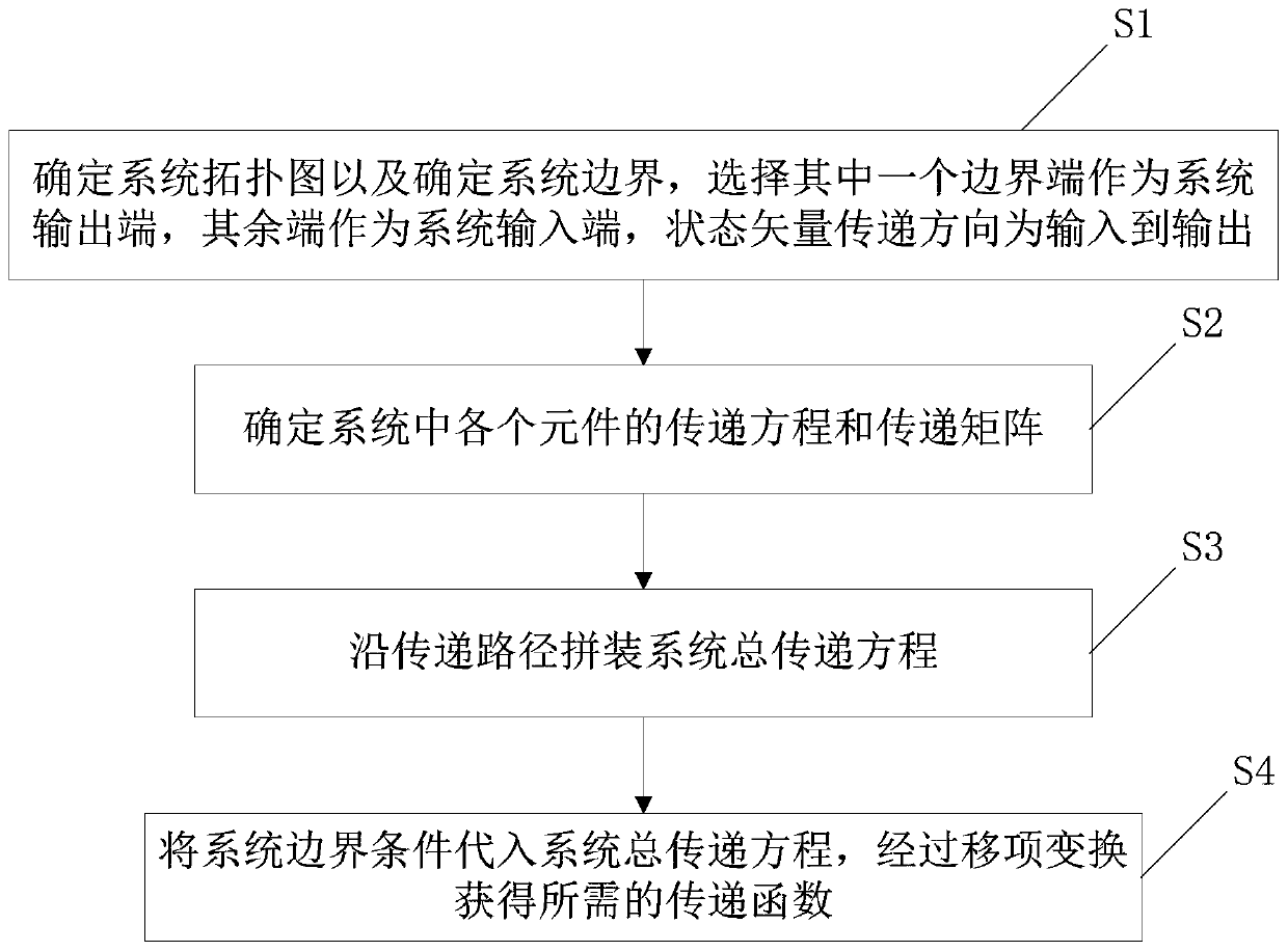
[0018] The invention discloses a method for solving the transfer function of the vehicle system based on the transfer matrix, please refer to figure 1 , the method includes:

[0019] Step S1, determining the system topology and determining the system boundary;

[0020] Step S2, determining the transfer equation and transfer matrix of each element in the system;

[0021] Step S3, assembling the total transfer equation of the system along the transfer path;

[0022] Step S4, substituting the boundary conditions of the system into the total transfer equation of the system, and obtaining the required transfer function through transposition transformation;

[0023] Further, in the step S1, after the system boundary is determined, one of the boundary terminals is selected as the system output terminal, and the remaining terminals are used as the sys...


PUM


Abstract

The invention discloses a vehicle system transfer function solving method based on a transfer matrix. The method comprises the steps that S1, determining a system topological graph and a system boundary; S2, determining a transfer equation and a transfer matrix of each element in the system; S3, assembling a system total transfer equation along a transfer path; and S4, introducing the system boundary condition into a system total transfer equation, and obtaining a required transfer function through item transfer transformation. According to the method, all steps of writing a dynamics differential equation of the whole system are not needed; in addition, the concept of multiple input hinge elements is provided, a controlled vehicle system element matrix library is perfected, and a transfermatrix of required elements can be directly selected from the matrix library when a vehicle system transfer function is calculated, so that the calculation process is more convenient and faster, and the programmable degree is higher.

Description

technical field [0001] The invention relates to a method for solving a vehicle system transfer function, in particular to a method for solving a vehicle system transfer function based on a transfer matrix. Background technique [0002] In the prior art, the traditional method of calculating the transfer function of a linear system is to establish the dynamic differential equation of the entire system, and obtain the transfer function from input to output through Laplace transform, but it is difficult to establish the overall dynamic equation of the system, Error-prone and other defects. Contents of the invention [0003] The technical problem to be solved by the present invention is to provide a vehicle system transfer function solution method based on the transfer matrix which is more convenient and easy to calculate, has a low error rate and good accuracy, and aims at the deficiencies of the prior art. [0004] In order to solve the above technical problems, the present...

Claims


Application Information

Patent Timeline
Patent Type & Authority Applications(China)
IPC IPC(8): G06F17/13G06F30/15G06F119/14
CPCG06F17/13
Inventor 孙露程志峰王一建刘晓丰
Owner CHANGCHUN INST OF OPTICS FINE MECHANICS & PHYSICS CHINESE ACAD OF SCI
Why Eureka
Try Eureka