Sludge dewatering and drying device and method

A sludge dewatering and drying technology, applied in chemical instruments and methods, water/sludge/sewage treatment, sludge treatment, etc., can solve the problems of high equipment investment and operating costs, easy blockage of feeding materials, and low dewatering efficiency. , to achieve the effect of good application value, good water absorption and high dehydration efficiency

Pending Publication Date: 2020-06-30
INST OF URBAN ENVIRONMENT CHINESE ACAD OF SCI
View PDF3 Cites 6 Cited by
  • Summary
  • Abstract
  • Description
  • Claims
  • Application Information

AI Technical Summary

Problems solved by technology

Chinese document CN105115271A discloses a belt dryer. The belt dryer includes four parts: a dryer shell, a dryer cavity, a transmission device, and a heating and drying system. There are inlet fan ports, circulation fan ports, exhaust fan ports, and moisture exhaust fan ports, which are suitable for drying Chinese herbal medicines, and solve the defects of traditional belt dryers that are easy to block when feeding and uneven cloth distribution.
[0004] A comprehensive analysis of the above patent documents shows that the belt dryer is used to realize sludge drying in one step, which leads to high equipment investment and operating costs, and it is difficult to solve the problems of sludge dehydration difficulties, fine particles, high viscosity, and high energy consumption. Problems, low dehydration efficiency, large environmental impact

Method used


Image

  • Sludge dewatering and drying device and method
  • Sludge dewatering and drying device and method

Examples


Embodiment

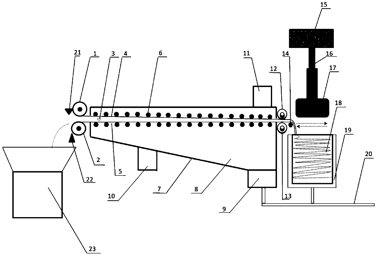
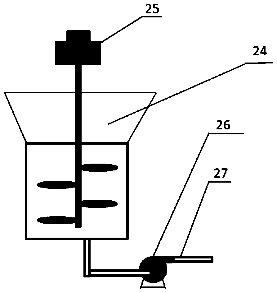
[0033] Example: see figure 1 and figure 2 , a sludge dehydration and drying device, including a heating pre-dehydration chamber 8, upper and lower layer filter cloths 4, 5 and a high-pressure dewatering assembly, the upper and lower layer filter cloths pass through the sludge conveying channel formed by the heating pre-dehydration chamber 8, and the upper , the lower layer of filter cloth 4,5 is fed and received along the channel, the heating pre-dehydration chamber 8 is provided with a feed inlet 3 for inputting sludge, and the outer sides of the upper and lower layer of filter cloth 4,5 are provided with a slide roller 6, and the heating pre-dehydration chamber 8 is provided with a feed port 3 for inputting sludge. The dehydration chamber is equipped with a flue gas inlet 11 to heat and adjust the sludge in the filter cloth interlayer on-line to realize heating pre-dehydration. One end of the heating pre-dehydration chamber 8 is provided with a high-pressure dehydration com...


PUM


Abstract

The invention discloses a sludge dewatering and drying device and method, and belongs to the technical field of sludge treatment, wherein the device comprises a heating pre-dewatering chamber, upper-layer filter cloth, lower-layer filter cloth and a high-pressure dewatering assembly, the upper-layer filter cloth and the lower-layer filter cloth penetrate through a sludge conveying channel formed by the heating pre-dewatering chamber; the upper-layer filter cloth and the lower-layer filter cloth are fed and collected along the channel; the heating pre-dewatering chamber is provided with a feeding hole for inputting sludge; sliding rollers are arranged on the outer sides of the upper-layer filter cloth and the lower-layer filter cloth; the heating pre-dewatering chamber is provided with a flue gas inlet for heating and conditioning sludge in a filter cloth interlayer on line to realize heating and pre-dewatering; a high-pressure dewatering assembly is arranged at one end of the heating pre-dewatering chamber and comprises a high-pressure dewatering tank and a matched hydraulic cylinder, a circulating material distribution mechanism is arranged on the high-pressure dewatering tank tofold the interlayer filter cloth in the high-pressure dewatering tank in a reciprocating mode, and the hydraulic cylinder presses the multiple layers of filter cloth for high-pressure dewatering. Deepdrying dewatering is achieved, the moisture content of the finally obtained sludge is less than 10%, and the device has the advantages of being high in dewatering efficiency, low in operation cost, high in practicability and the like.

Description

technical field [0001] The invention discloses a sludge dehydration and drying device and method, and belongs to the technical field of sludge treatment according to the International Patent Classification (IPC). Background technique [0002] For traditional ordinary belt filter press dewatering machines, deep dehydration cannot be achieved due to the low pressing force between the upper and lower power tension filter belts, and the moisture content of sludge after dehydration is generally around 80%, which is high. The sludge will not only lead to the cost of automobile transportation, but also increase the cost of subsequent disposal of sludge. Although the traditional belt dryer also has a heating device, in order to achieve the goal of drying and dehydration, the drying time is getting longer and longer, the drying efficiency is low, and when the waste heat and energy of the flue gas are used, the drying device is bulky and the investment and operation costs are high; an...

Claims


Application Information

Patent Timeline
Patent Type & Authority Applications(China)
IPC IPC(8): C02F11/143C02F11/13C02F11/123
CPCC02F11/123C02F11/13C02F11/143
Inventor 余广炜汪印
Owner INST OF URBAN ENVIRONMENT CHINESE ACAD OF SCI
Why Eureka
Try Eureka