Metal grid structure, touch screen and touch display screen

A technology of metal grid and touch screen, applied in the field of touch screen and touch screen, metal grid structure, can solve the limitation of metal lead production process capacity, narrow frame and touch performance can not be satisfied at the same time, poor and other issues to achieve the effect of narrow border effect

Pending Publication Date: 2020-07-03
SHENZHEN LAIBAO HI TECH
View PDF0 Cites 0 Cited by
  • Summary
  • Abstract
  • Description
  • Claims
  • Application Information

AI Technical Summary

Problems solved by technology

However, metal leads are limited by the production process capability, and it is generally difficult to further optimize
The traditional OGS touch screen uses indium tin oxide (ITO) to make the touch electrode layer. The resistivity of the sheet resistance of indium tin oxide (ITO) usually ranges from tens to hundreds of ohms, because of its large resistance and high conductivity. Poor, reducing or reducing the size of the display area is also difficult to meet the requirements of touch driver IC design, adding more difficulties to the design of touch driver IC
The narrow frame design of the touch screen can only be achieved by reducing the number of touch electrode channels of the touch screen, but this design reduces the basic touch performance of the product
[0005] In view of the above-mentioned technical problems that the narrow bezel and touch performance cannot be satisfied at the same time, how to take into account the performance of both parties has become a subject that needs to be overcome

Method used


Image

  • Metal grid structure, touch screen and touch display screen
  • Metal grid structure, touch screen and touch display screen
  • Metal grid structure, touch screen and touch display screen

Examples


Embodiment Construction

[0031] In order to illustrate the touch screen provided by the present invention and the manufacturing method thereof, a detailed description will be given below in conjunction with the accompanying drawings and the written description of the embodiments.

[0032] The invention provides a metal grid structure and a touch screen adopting the metal grid structure.

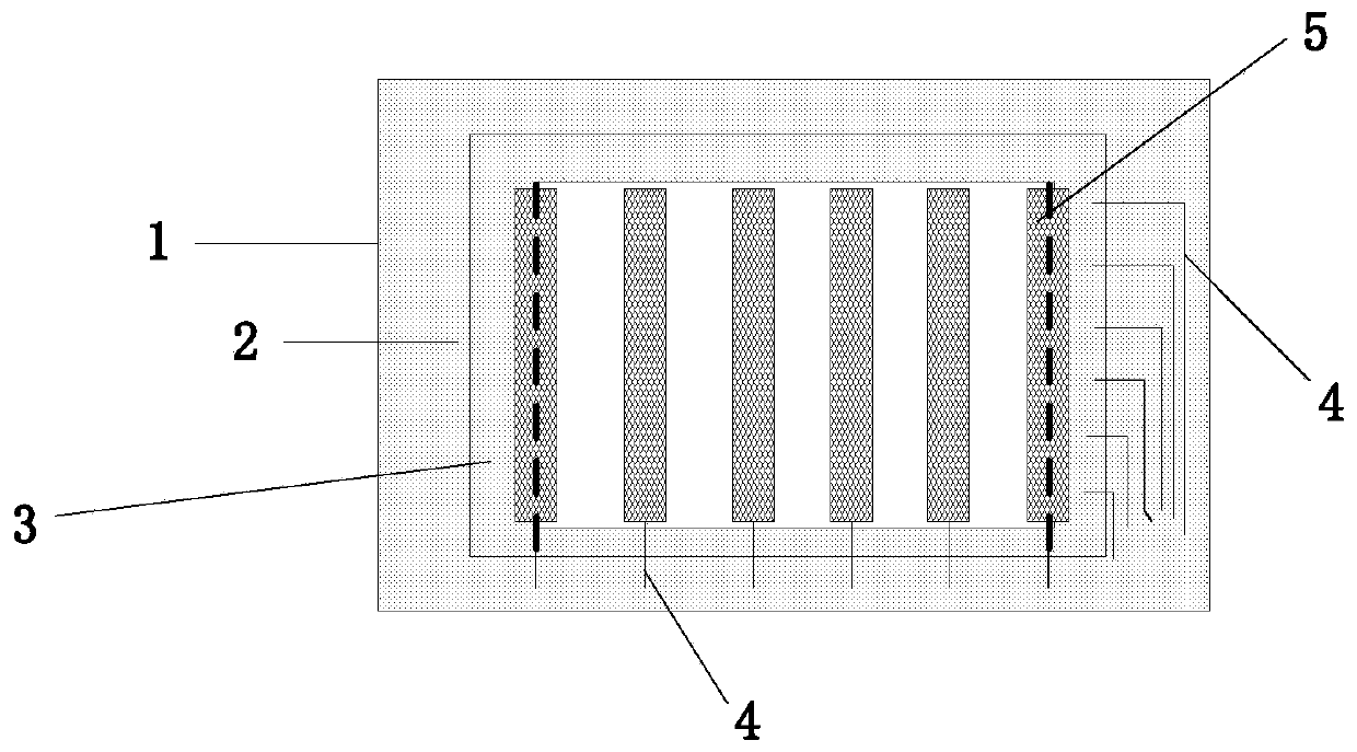
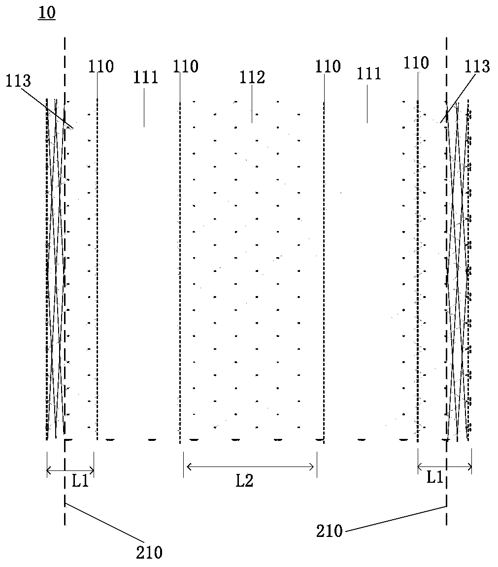
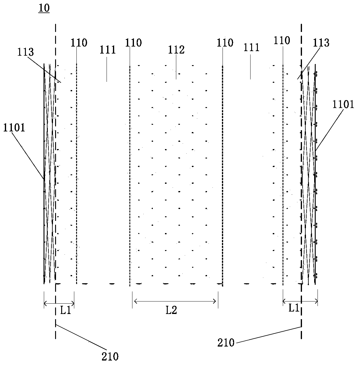
[0033] In a specific embodiment, the metal grid structure can be designed as a first metal grid structure 10 or a second metal grid structure 20 . A touch screen is formed by laminating the first metal grid structure 10 and the second metal grid structure 20 .

[0034] Such as figure 2 As shown, the first metal grid structure 10 provided by the embodiment of the present invention includes: metal grid lines formed by crossing metal wires, and the metal grid lines are separated by break lines 110 to form a spacer The first touch electrode channel of the row and the first Dummy block 111, the first touch electrode ch...


PUM


Abstract

The invention relates to the technical field of touch control, and provides a metal grid structure, a touch screen and a touch display screen. The metal grid structure comprises metal grid lines formed by intersecting a plurality of metal lines, the metal grid lines are separated by fracture lines one by one to form touch electrode channels and Dummy blocks, the touch electrode channels and the Dummy blocks are arranged at intervals, the touch electrode channels are connected with driving equipment, and the Dummy blocks are not connected with the driving equipment and only have an optical matching effect. The touch electrode channel comprises an edge sub-touch electrode and an in-plane sub-touch electrode. Wherein the outer side parts of the edge sub-touch electrodes are covered by the BM,the metal grid lines, covered by the BM, of the edge sub-touch electrodes are denser than the metal grid lines of the in-plane sub-touch electrodes in design, and the width of the edge sub-touch electrodes is smaller than that of the in-plane sub-touch electrodes. Due to the design effect of the metal grid lines, the edge sub-touch electrodes and the in-plane sub-touch electrodes can generate similar electrical properties in the aspects of resistance and capacitance, and the basic touch performance cannot be affected.

Description

technical field [0001] The present invention relates to the field of touch technology, in particular to the field of touch display technology, in particular to a metal grid structure, a touch screen and a touch screen. Background technique [0002] At present, the touch display technology industry pays more and more attention to the design of the product frame, and strives to compress the frame (ie black frame) of the touch screen as much as possible to obtain a more market-competitive product. [0003] Such as figure 1 As shown, the current touch display screen includes a touch module 1 and a display module 2 bonded through an adhesive layer (not shown), and the size of the touch module 1 is slightly larger than that of the display module 2. size, the edge of the touch module 1 is covered by black shielding material 3 (BM) (mainly to shield the edge metal leads 4), so that the touch module is divided into a display area and a non-display area, and the non-display area is c...

Claims


Application Information

Patent Timeline
Patent Type & Authority Applications(China)
IPC IPC(8): G06F3/041
CPCG06F3/0412
Inventor 王士敏周威云宋小来李计考朱泽力
Owner SHENZHEN LAIBAO HI TECH
Why Eureka
Try Eureka