Charging circuit and charging device

A charging circuit and resistor technology, applied in battery circuit devices, circuit devices, charging/discharging current/voltage regulation, etc., can solve problems such as complicated operation of external equipment, and achieve the effect of improving the complicated operation

Active Publication Date: 2022-03-29
VIVO MOBILE COMM CO LTD
View PDF10 Cites 0 Cited by
  • Summary
  • Abstract
  • Description
  • Claims
  • Application Information

AI Technical Summary

Problems solved by technology

[0004] The invention provides a charging device to solve the problem of complicated operation during the charging test of external equipment

Method used


Image

  • Charging circuit and charging device
  • Charging circuit and charging device

Examples


Embodiment Construction

[0013] In order to make the purpose, technical solution and advantages of the present invention clearer, the technical solution of the present invention will be clearly and completely described below in conjunction with specific embodiments of the present invention and corresponding drawings. Apparently, the described embodiments are only some of the embodiments of the present invention, but not all of them. Based on the embodiments of the present invention, all other embodiments obtained by persons of ordinary skill in the art without making creative efforts belong to the protection scope of the present invention.

[0014] In the description of the present application, it should be understood that the terms "center", "longitudinal", "transverse", "length", "width", "thickness", "upper", "lower", "front", " The orientation or positional relationship indicated by "rear", "left", "right", "vertical", "horizontal", "top", "bottom", "inner", "outer", etc. is based on the orientati...


PUM


Abstract

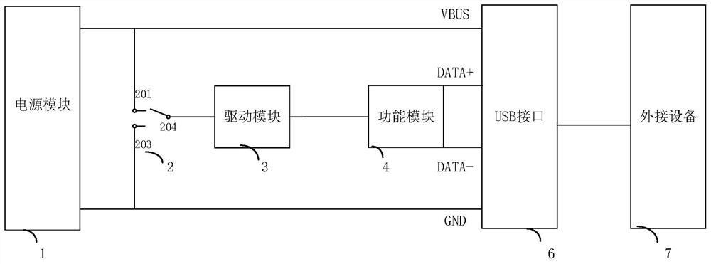
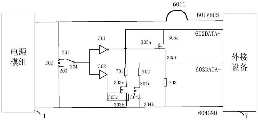
The invention discloses a charging device, comprising: a power module, a switch module, a drive module, a control module, and a USB interface, the first fixed end of the switch module is connected to the positive end of the power module, the second fixed end of the switch module is connected to the power module The negative terminal of the switch module is connected to the input terminal of the drive module, the output terminal of the drive module is connected to the input terminal of the control module, and the output terminal of the control module is respectively connected to the DATA+ pin of the USB interface and the DATA‑pin of the USB interface. Pin connection, the VBUS pin of the USB interface is connected to the positive end of the power module, the GND pin of the USB interface is connected to the negative end of the power module; when the movable end of the switch module is connected to the first fixed end, DATA+ The pin and the DATA-pin are connected to the GND pin of the USB interface through a resistor; when the active end of the switch module is connected to the second fixed end, the DATA+ pin and the DATA-pin are short-circuited. The invention can solve the problem of complicated operation during the charging test of the external device.

Description

technical field [0001] The invention relates to the technical field of electronic communication, in particular to a charging circuit and a charging device. Background technique [0002] At present, the electronic devices on the market are all devices with their own batteries as the power source, and the problem that such power devices need to face is charging. In order to ensure the safety and practicability of the product, it is often necessary to conduct a charging test on the electronic device to ensure that the electronic device can be safely charged under different charging products. The current popular charging methods generally include: charging with a travel charger, charging with a USB port on the PC side, and charging with a cigarette lighter. [0003] The interface forms and electrical characteristics of various charging methods are different, and the charging currents provided are also different. At present, there is no corresponding interface that can completel...

Claims


Application Information

Patent Timeline
Patent Type & Authority Patents(China)
IPC IPC(8): H02J7/00G01R1/04
CPCH02J7/007G01R1/0416
Inventor 高军
Owner VIVO MOBILE COMM CO LTD
Why Eureka
Try Eureka