A turbine generator

A technology for turbine power generation and equipment, which is applied in wind power generation, mechanical equipment, engines, etc., can solve the problems of the reduction of power generation efficiency of turbine generators, and achieve the effect of avoiding difficult removal.

Active Publication Date: 2021-05-07
新昌县兴欧智能科技有限公司
View PDF0 Cites 0 Cited by
  • Summary
  • Abstract
  • Description
  • Claims
  • Application Information

AI Technical Summary

Problems solved by technology

[0003] Since the internal rotating turbine of the turbogenerator is always connected with the outside world, when the turbogenerator used for fishing boats at sea stops working, it is easy for the sea breeze to enter the interior of the turbogenerator through the air vent. The sea salt layer is formed, which leads to a decrease in the power generation efficiency of the turbine generator

Method used


Image

  • A turbine generator
  • A turbine generator
  • A turbine generator

Examples


Embodiment 1

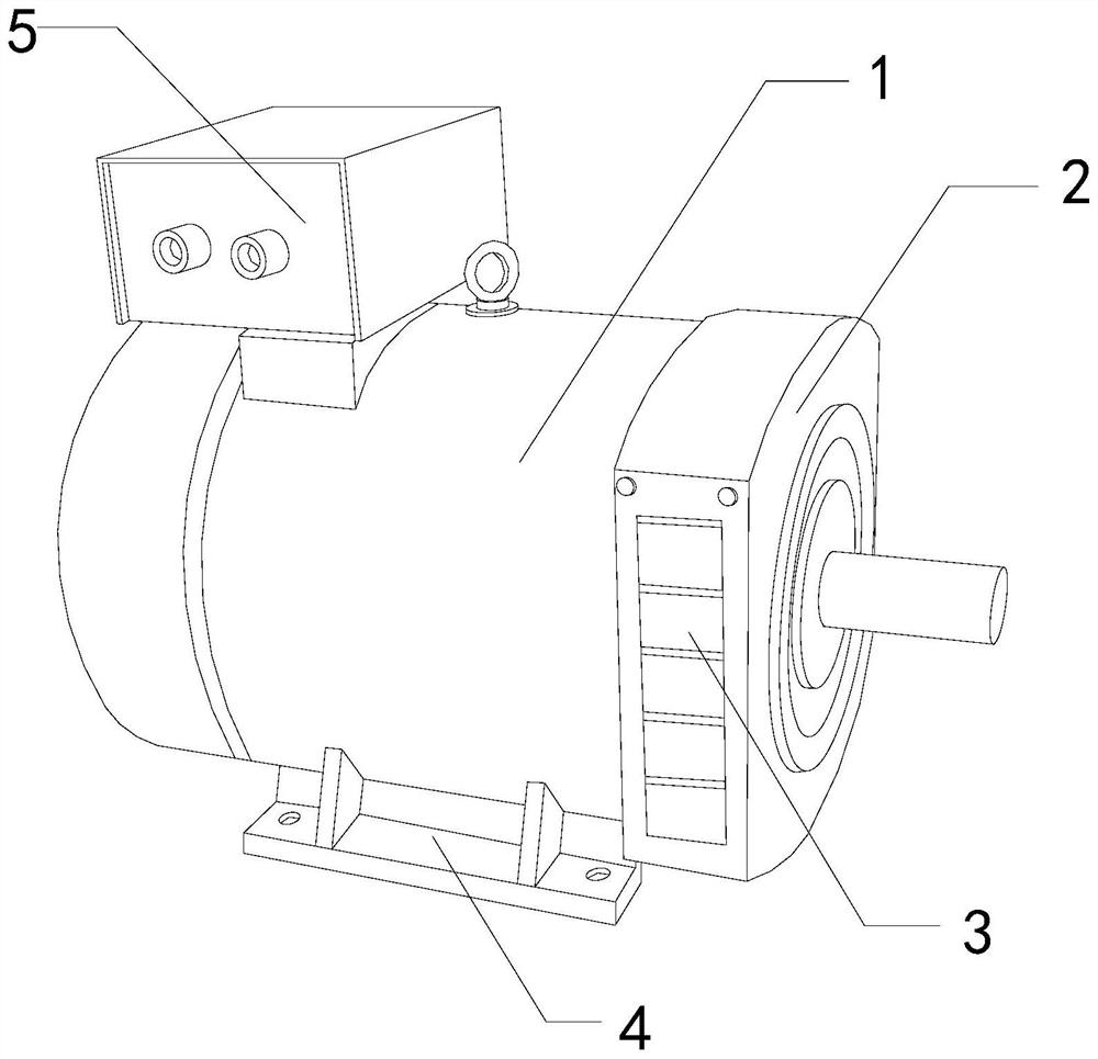
[0026] For example figure 1 -example Figure 5 Shown:

[0027] The invention provides a turbine power generation equipment, the structure of which includes a generator 1, a turbine mechanism 2, an air vent 3, a base 4, and a connection box 5. The turbine mechanism 2 is embedded in the right end of the generator 1, and the base 4 is welded at the bottom of the generator 1, the electrical connection box 5 is installed at the upper end of the generator 1, and the vent 3 and the turbine mechanism 2 are an integrated mechanism.

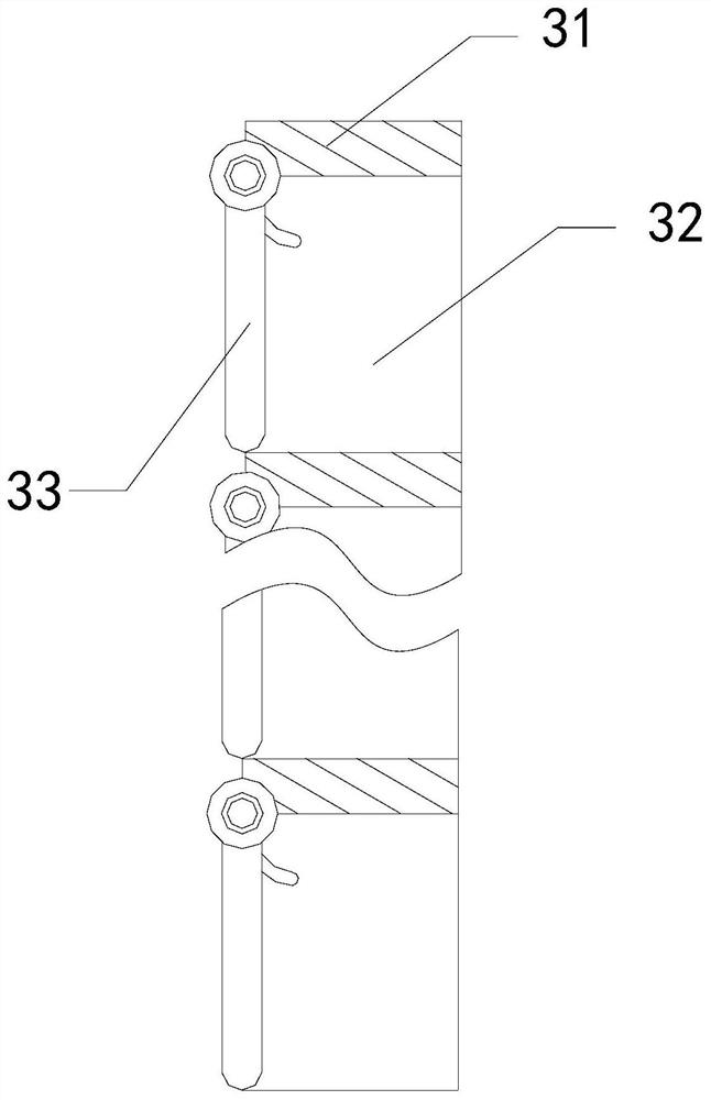
[0028] Wherein, the air vent 3 includes a frame body 31, an exhaust cavity 32, and a swing plate 33, the exhaust cavity 32 and the frame body 31 are an integrated structure, and the swing plate 33 is hingedly connected with the frame body 31, when there is The airflow pushes the swinging plate 33 outwards through the exhaust chamber 32 so that it can swing upwards, so that the airflow can be discharged. When the thrust of the airflow is lost, the swingin...

Embodiment 2

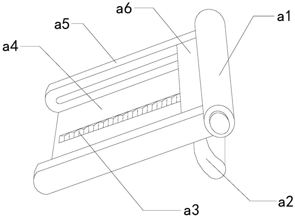
[0034] For example Image 6 -example Figure 8 Shown:

[0035]Wherein, the protection surface a3 includes a opening and closing plate a31, a sliding block a32, a fixed rod a33, a transmission rod a34, and a connecting rod a35. The sliding block a32 is in clearance fit with the opening and closing plate a31. Between the plywood a31, one end of the transmission rod a34 is connected with the left end of the fixed rod a33, and the other end of the transmission rod a34 is movably engaged with the left end of the connecting rod a35, and the connecting rod a35 is hingedly connected with the sliding block a32, There are two fixed rods a33, which are symmetrically distributed on the inner side of the opening and closing plate a31. When the opening and closing plate a31 is folded and closed by external force, the transmission rod a34 can be closed synchronously, so that the sliding block on the connecting rod a35 a32 can be attached to the inner side of the opening and closing plate a...


PUM


Abstract

The invention discloses a turbine power generation equipment, the structure of which comprises a generator, a turbine mechanism, an air vent, a base, and a connection box. The box is installed on the upper end of the generator, and the air vent and the turbine mechanism are an integrated mechanism. When the turbine mechanism stops working, the swing plate on the air vent will return to the closed state, thereby resisting the sea breeze on the outer surface of the swing plate, so The sea breeze brings the sea salt buckets and attaches them to the outer surface of the swing plate, and when the linkage plate slides forward, the protection surface is squeezed, so that the opening and closing plates on the protection surface can be folded and closed, so that the transmission on the protection surface The rod can be closed synchronously with the opening and closing plate, so that the connecting rod connected with the transmission rod can drive the sliding block to scrape off the sea salt attached to the inner side of the opening and closing plate.

Description

technical field [0001] The invention relates to the field of power generation equipment, in particular to a turbine power generation equipment. Background technique [0002] The turbine generator mainly rotates at high speed through the internal rotating turbine, and then cooperates with the internal energy converter to convert the capacity generated by the rotating turbine into electrical energy, so that it can provide operating energy for electrical equipment. It is a common device in life, based on According to the above description, the inventors found that the existing turbine power generation equipment mainly has the following deficiencies, for example: [0003] Since the internal rotating turbine of the turbogenerator is always connected with the outside world, when the turbogenerator used for fishing boats at sea stops working, it is easy for the sea breeze to enter the interior of the turbogenerator through the air vent. The sea salt layer is formed, which leads to...

Claims


Application Information

Patent Timeline
Patent Type & Authority Patents(China)
IPC IPC(8): F03D9/25F03D80/00F03D80/55
CPCF03D9/25F03D80/00F03D80/55Y02E10/72
Inventor 陈国荣
Owner 新昌县兴欧智能科技有限公司
Why Eureka
Try Eureka