Printer shaft with heat dissipation structure

A heat dissipation structure and printer technology, applied in printing devices, printing, etc., can solve problems such as printing can not be carried out normally, the printing shaft does not dissipate heat, and affect the printing effect, etc., and achieve simple and fast connection, improve efficiency, and prolong service life Effect

Active Publication Date: 2020-09-08
INNOVATION PRECISION SUZHOU
View PDF18 Cites 1 Cited by
  • Summary
  • Abstract
  • Description
  • Claims
  • Application Information

AI Technical Summary

Problems solved by technology

[0004] Aiming at the deficiencies of the prior art, the present invention provides a printer shaft with a heat dissipation structure, which solves the problem that the existing printing shaft has no heat dissipation measures, which will cause the printing to not proceed normally and affect the printing effect. At the same time, the existing printer The shaft is an integral fixed structure, which is not easy to disassemble, and it is difficult to repair and replace

Method used


Image

  • Printer shaft with heat dissipation structure
  • Printer shaft with heat dissipation structure
  • Printer shaft with heat dissipation structure

Examples


Embodiment 1

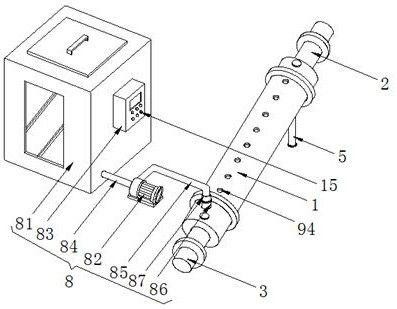
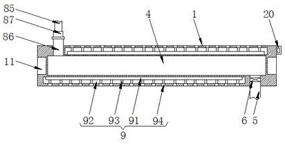
[0035]A printer shaft with a heat dissipation structure, comprising a shaft body 1 and two rotating shafts 2, the ends of the two rotating shafts 2 facing away from each other are fixedly connected with a connecting shaft 3, a cavity 4 is opened inside the shaft body 1, and the cavity The bottom of the right side of the cavity 4 is connected with the water outlet pipe 5, the bottom end of the water outlet pipe 5 runs through the shaft body 1 and extends to the outside of the shaft body 1, the top of the inner wall of the connecting pipe 86 and the outer surface of the threaded head 87 are fixedly connected with a sealing ring 10. A sealing ring 10 is provided at the joint between the connecting pipe 86 and the threaded head 87 to improve the sealing performance and prevent water overflow. The inside of the outlet pipe 5 is fixedly connected with a solenoid valve 6, and the top of the right side of the shaft body 1 is fixedly connected with a temperature sensor 7. , the model of...

Embodiment 2

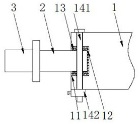
[0037] A printer shaft with a heat dissipation structure, comprising a shaft body 1 and two rotating shafts 2, both ends of the shaft body 1 are provided with fixing grooves 11 matching the rotating shafts 2, and the inner walls of the fixing grooves 11 are fixedly connected with The rubber pad 12, the surface of the rotating shaft 2 near the end of the shaft body 1 is fixedly connected with a rubber ring 13, and the rubber pad 12 and the rubber ring 13 increase the friction between the rotating shaft 2 and the fixed groove 11 while improving the sealing performance, thereby To improve the stability of the connection, the rubber pad 12 and the rubber ring 13 can be replaced to ensure elasticity. Both ends of the shaft body 1 are fixedly connected with a disassembly mechanism 14. It is set as a detachable connection, which is convenient for maintenance and replacement. It can be disassembled without using tools, and the operation is simple. The disassembly mechanism 14 includes ...

Embodiment 3

[0039] A printer shaft with a heat dissipation structure, including a shaft body 1 and two rotating shafts 2, the shaft body 1 includes a base layer 101, the top of the base layer 101 is sprayed with a high temperature resistant coating 102, and the high temperature resistant coating 102 is specifically silicone high temperature resistant coating, and the top of the high temperature-resistant coating 102 is sprayed with a wear-resistant coating 103, the wear-resistant coating 103 is made of epoxy resin material, the high-temperature resistant coating 102 and the wear-resistant coating 103 improve the resistance of the shaft body 1 Abrasion performance and high temperature resistance performance prolong the service life of the printer shaft. The ends of the two rotating shafts 2 facing away from each other are fixedly connected with the connecting shaft 3. The inside of the shaft body 1 is provided with a cavity 4, and the right side of the cavity 4 The bottom is connected with ...


PUM


Abstract

The invention discloses a printer shaft with a heat dissipation structure and relates to the technical field of printers. The printer shaft comprises a shaft body and two rotation shafts. Connection shafts are fixedly connected to the ends, away from each other, of the two rotation shafts, a cavity is formed in the shaft body, and a water outlet pipe communicates with the bottom of the right sideof the cavity. An electromagnetic valve is fixedly connected into the water outlet pipe, a temperature sensor is fixedly connected to the top of the right side of the shaft body, and the surface of the shaft body is provided with a first heat dissipation mechanism. According to the printer shaft with the heat dissipation structure, a first heat dissipation mechanism comprises a water tank and a water pump, a tank body is fixedly connected to the right side of the water tank, the temperature sensor is fixedly connected to the top of the right side of the shaft body, and a water pumping pipe communicates with the bottom of the right side of the water tank. When the printer shaft overheats, a water pump pumps cold water in the water tank and injects the cold water into the cavity of the printer shaft so as to cool the shaft body, it is guaranteed that the printing work can be normally performed, and the printing effect cannot be influenced.

Description

technical field [0001] The invention relates to the technical field of printers, in particular to a printer shaft with a heat dissipation structure. Background technique [0002] The printer is one of the output devices of the computer. It is used to print the computer processing results on the relevant media. There are three indicators to measure the quality of the printer: printing resolution, printing speed and noise. There are many types of printers. There are striking actions, divided into impact printers and non-impact printers, according to the structure of printed characters, divided into full-size character printers and dot-matrix character printers, according to the way a line of characters is formed on paper, divided into serial printers and line printers Printers, according to the technology used, are divided into cylindrical, spherical, inkjet, thermal, laser, electrostatic, magnetic, light-emitting diode and other printers. Recognizable numbers, letters, symbo...

Claims


Application Information

Patent Timeline
Patent Type & Authority Applications(China)
IPC IPC(8): B41J29/377B41J29/00
CPCB41J29/377B41J29/00
Inventor 张行周元锋邓立新
Owner INNOVATION PRECISION SUZHOU
Why Eureka
Try Eureka