Refrigerator and quick-freezing method thereof

A technology for refrigerators and quick-freezing rooms, which is applied to household refrigerators, coolers, lighting and heating equipment, etc. It can solve the problems of high manufacturing cost, complicated structure, and affecting the effect of quick-freezing, and achieves low manufacturing cost, small occupied volume, The effect of stable performance

Pending Publication Date: 2020-09-18
HEFEI SNOWKY ELECTRIC
View PDF0 Cites 1 Cited by
  • Summary
  • Abstract
  • Description
  • Claims
  • Application Information

AI Technical Summary

Problems solved by technology

[0003] The disadvantage of the above-mentioned refrigeration system is that at least two fans and their corresponding air doors, air ducts, etc. need to be provided, especially when it is applied in a multi-chamber refrigerator with a variable room, not only the structure is complicated, but the manufacturing cost is high. problems, and will directly affect the effect of quick freezing
[0004] Some refrigerators realize temperature control through a damper or mother-to-child damper, but this kind of damper is generally placed in the cold storage room, which cannot meet the requirements of temperature division in the freezing room, and cannot meet the temperature control of more than two refrigerators.

Method used


Image

  • Refrigerator and quick-freezing method thereof
  • Refrigerator and quick-freezing method thereof
  • Refrigerator and quick-freezing method thereof

Examples


Embodiment 1

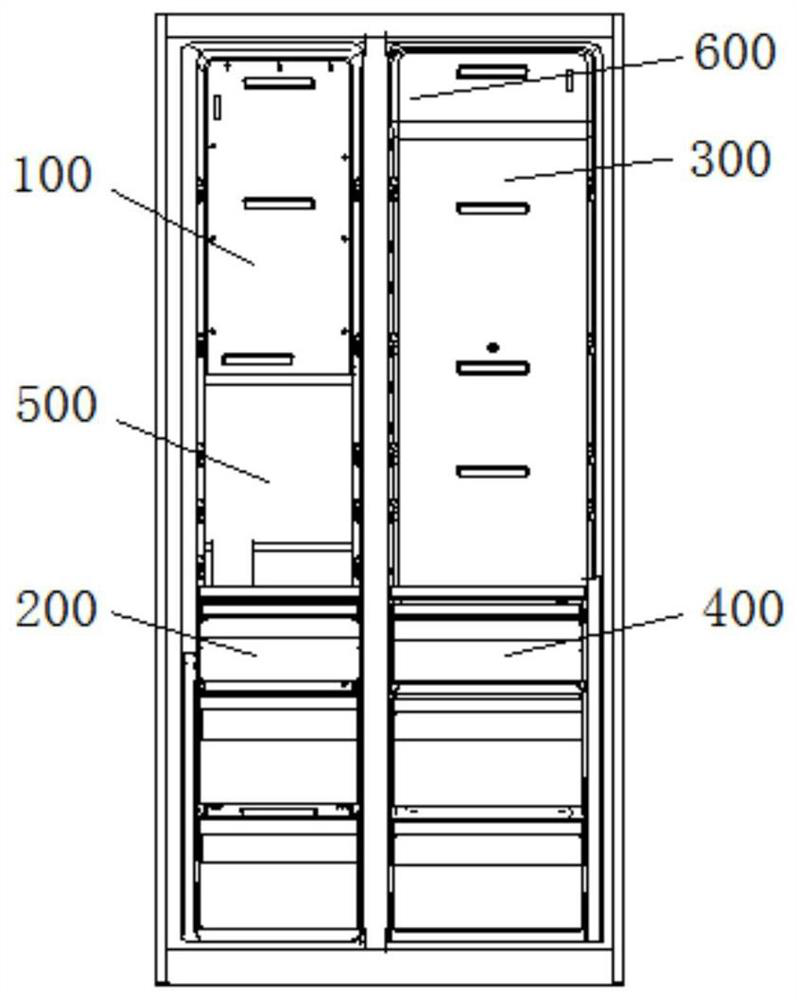
[0022] In this example, see Figure 4 , the damper assembly 5 includes a mother damper 51 arranged on the first air passage 1 and the second air passage 2, and a single damper 52 arranged on the third air passage 3, wherein the first air passage 1 and the second air passage The air inlets of channel 2 are all arranged above the mother-child damper 51, the air inlet of the third air duct 3 is arranged below the single damper 52, and the fan 4 is located in the space formed by the mother-child damper 51 and the single damper 52, and is located in the child Below the mother damper 51 and above the single damper 52 , the sub-mother damper 51 includes a motor 6 and dampers 7 arranged along both sides of the motor 6 and correspondingly connected to the air inlets of the first air duct 1 and the second air duct 2 .

[0023] When in use, the single motor 6 in the mother-child damper 51 can drive the left and right dampers 7 to move, and combined with the single damper 52, it can not o...

Embodiment 2

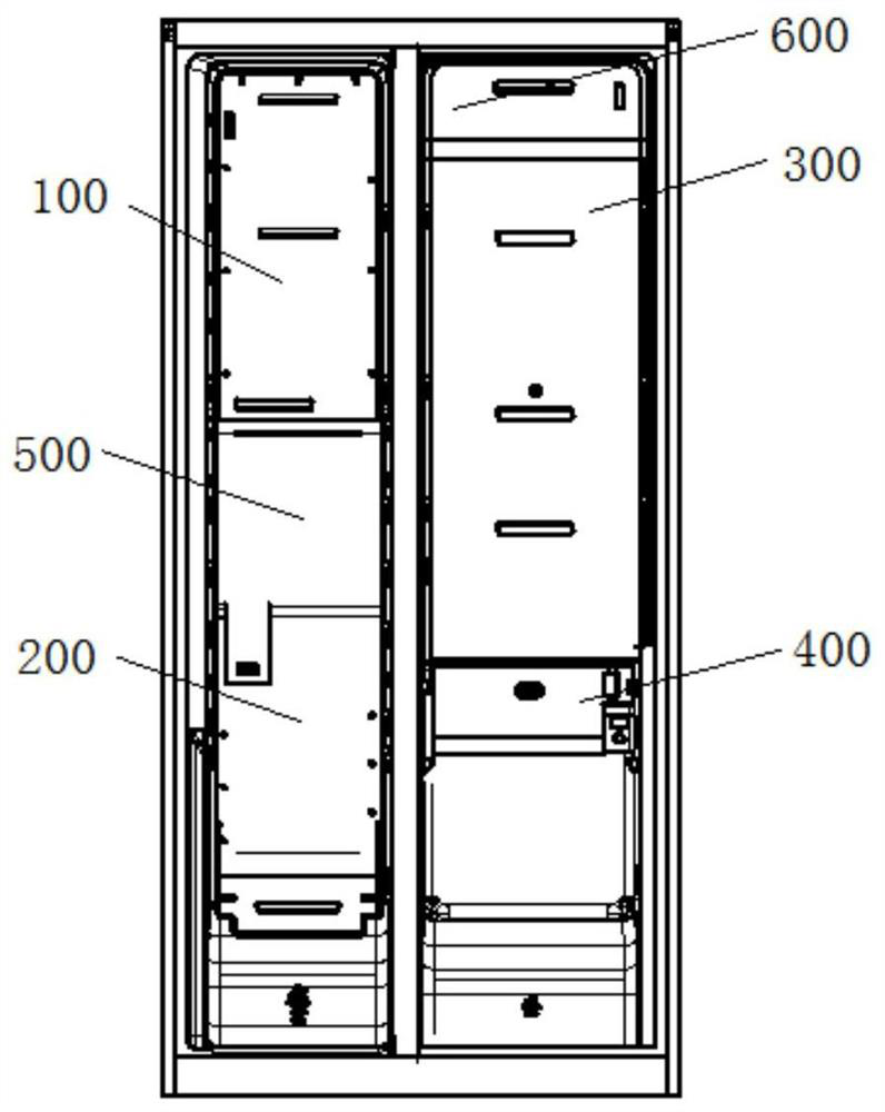
[0025] In this example, see Figure 5 , the damper assembly 5 includes a reverse damper 53 arranged on the first air passage 1 and the third air passage 3, and a single damper (not shown) arranged on the second air passage 2, wherein the first air passage 1 The air inlet of the third air duct 3 is set above the reverse damper 53, the air inlet of the third air duct 3 is set below the reverse damper 53, the single damper (not shown) is set on the rear side of the variable temperature compartment 400, and the fan 4 is located on the reverse side. In the space formed by the damper 53 and the single damper (not shown), and located on the inner side of the reverse damper 53, above the single damper (not shown), the reverse damper 53 includes the motor 6 and is arranged up and down along the motor 6, and The air inlets of the first air passage 1 and the third air passage 3 correspond to the dampers 7 that are connected.

[0026] When in use, the single motor 6 in the reverse damper...

Embodiment 3

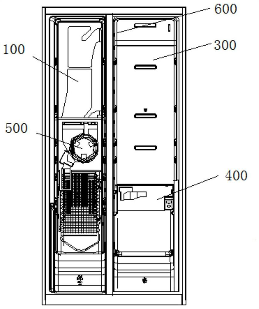
[0028] In this example, see Figure 6 , the damper assembly 5 includes a one-to-three damper 54 arranged on the first air duct 1, the second air duct 2 and the third air duct 3, wherein the air inlets of the first air duct 1 and the second air duct 2 are all set Above the one-to-three damper 54, the air inlet of the third air passage 3 is arranged on the side of the one-to-three damper 54, the fan 4 is located below the one-to-three damper 54, and the one-to-three damper 54 includes a motor 6 and One side of the motor 6 is arranged at intervals, and the damper 7 connected to the air inlets of the first air duct 1 and the third air duct 3 is arranged vertically with the air inlet of the first air duct 1, correspondingly connected to the second air duct 2 The damper 7 of the air inlet.

[0029] When in use, the single motor 6 in the one-to-three damper 54 can drive the three side dampers 7 to move, which not only has a reasonable layout, can better control the direction of cold...


PUM


Abstract

The invention provides a refrigerator and a quick-freezing method thereof. The refrigerator comprises a quick-freezing chamber arranged in a freezing chamber and a variable-temperature chamber arranged in a refrigerating chamber; a single refrigerating system is arranged in the freezing chamber, and the single refrigerating system comprises a first air duct communicating with the freezing chamber,a second air duct communicating with the variable-temperature chamber and a third air duct communicating with the quick-freezing chamber; fans and an air door assembly are arranged among the first air duct, the second air duct and the third air duct, and the air door assembly is used for controlling air inlets of the first air duct, the second air duct and the third air duct to be opened and closed; the first air duct is connected with the air inlet of the refrigerating chamber, and an air door of the refrigerating chamber is arranged at the air inlet of the refrigerating chamber; and the quick-freezing method comprises the step that opening and closing of air inlets of the first air duct, the second air duct and the third air duct are adjusted by controlling the air door assembly. According to the refrigerator and the quick-freezing method thereof, configuration requirements of four temperature zones of freezing, cold storage, quick freezing and temperature changing are met through the single refrigerating system, and the refrigerator has the advantages of being small in occupied size, stable in performance and low in manufacturing cost.

Description

technical field [0001] The invention belongs to the technical field of refrigerators, and in particular relates to a refrigerator and a quick-freezing method for the refrigerator. Background technique [0002] With the improvement of living standards, people have higher and higher requirements for food preservation, especially the food stored in the freezer compartment, which sometimes needs to be frozen quickly to prevent damage to the food cell wall due to too slow freezing speed. In the prior art, a refrigerator with a quick-freezing function is often provided with a quick-freezing compartment, and such a refrigerator includes a first fan, a second fan, an evaporator, a first air duct, and a second air duct. Wherein, the first air duct communicates with the freezing compartment, and the second air duct communicates with the quick-freezing compartment. In general cooling conditions, if the freezer compartment of the refrigerator needs to be refrigerated, the first fan wor...

Claims


Application Information

Patent Timeline
Patent Type & Authority Applications(China)
IPC IPC(8): F25D11/02F25D17/08F25D17/04F25D29/00
CPCF25D11/02F25D17/045F25D17/08F25D29/00F25D2317/06F25D2317/067
Inventor 吴刚张鑫高方永
Owner HEFEI SNOWKY ELECTRIC
Why Eureka
Try Eureka