Intercooling humidifying device and fuel cell system applying same

A humidification device and heat exchange device technology, applied in fuel cells, fuel cell additives, fuel cell heat exchange and other directions, can solve the problems of complex layout, increased pipeline flow resistance, large space occupation, etc., to increase the mutual contact area , the effect of increasing airflow capacity and improving overall efficiency

Pending Publication Date: 2020-09-29
ZHONGSHAN BROAD OCEAN
View PDF0 Cites 5 Cited by
  • Summary
  • Abstract
  • Description
  • Claims
  • Application Information

AI Technical Summary

Problems solved by technology

[0003] The current air intake systems of fuel cells are arranged with independent intercoolers and humidifiers. For example, in the patent CN210467989 U, the independently arranged intercoolers and humidifiers require many pipelines to be connected to each other, and the arrangement is complicated and takes up space. , resulting in increased pipeline flow resistance and increased system risk
[0004] In addition, in order to solve the problem of large space occupation, the intercooler module is installed on one side of the humidification module. The contact area between the cold module and the humidification module is small, the airflow through is small, the efficiency is low, and the length is long

Method used


Image

  • Intercooling humidifying device and fuel cell system applying same
  • Intercooling humidifying device and fuel cell system applying same
  • Intercooling humidifying device and fuel cell system applying same

Examples


Embodiment 1

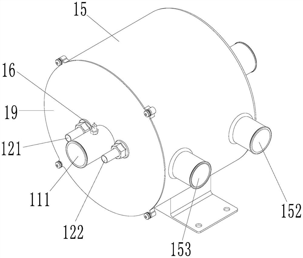
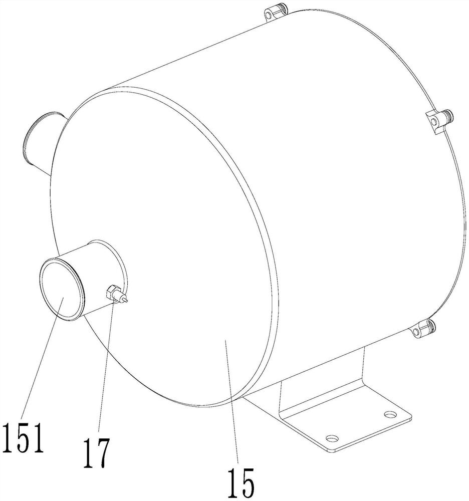
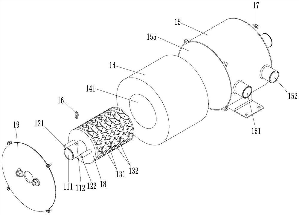
[0044] Such as Figure 1 to Figure 15As shown, this embodiment provides an intercooling and humidifying device, which is characterized in that it includes an air intake pipe 11, a heat exchange device 13, a humidification module 14 and a sleeve shell 15, and the heat exchange device 13 is set on the air intake pipe 11, the humidification module 14 is set outside the heat exchange device 13, the sleeve shell 15 is set outside the humidification module 14, and one end of the sleeve shell 15 is provided with a first air outlet 151, and the dry hot air flows from the air intake duct 11 One end enters and flows out radially, and after the cooling treatment of the heat exchange device 13 and the humidification treatment of the humidification module 14, the humid air formed at a low temperature flows out from the first air outlet 151. This structure will intercool and humidify the The function is integrated, the structure is simple and compact, occupies less space in the overall layo...

Embodiment 2

[0060] Such as Figure 16 with Figure 17 As shown, a fuel cell system includes a fuel cell stack module, a fuel cell system controller, a coolant circulation system, an air intake system, a hydrogen supply system, and an intercooling and humidifying device, and the air intake system includes an air filter , an air flow meter and an air compressor, characterized in that: the intercooling and humidifying device is the intercooling and humidifying device described in any one of claims 1 to 11, and the air enters the air after passing through the air filter and the air flow meter. Compressor, the air compressor controller controls the air compressor to compress the incoming air from the first air inlet 111 of the intercooling and humidifying device to enter through the heat exchange device 13 to exchange heat between the air and the cooling liquid, and then enter The humidification module 14 humidifies the passing air and discharges it from the first air outlet 151, and then inp...


PUM


Abstract

The invention discloses an intercooling humidifying device and a fuel cell system applying the same. The device comprises an air inlet pipeline, a heat exchange device, a humidifying module and a sleeve shell, the heat exchange device sleeves the air inlet pipeline; the humidifying module sleeves the heat exchange device; the humidifying module is sleeved with the sleeve shell; a first air outletis formed in one end of the sleeve shell; dry hot air enters from one end of the air inlet pipeline and flows out in the radial direction, the cooling treatment of the heat exchange device and the humidification treatment of the humidifying module are carried out, low-temperature humid air is formed, and the low-temperature humid air flows out of the first air outlet. The structure integrates thefunctions of intercooling and humidifying, the device is simple in structure, compact and small in occupied overall layout space of the fuel cell system, increases the mutual contact area of the heatexchange device and the humidifying module, increases the airflow circulation capacity, improves the overall efficiency of the fuel cell system, reduces parts and reduces the cost.

Description

Technical field: [0001] The invention relates to an intercooling and humidifying device and a fuel cell system for its application. Background technique: [0002] The fuel cell system includes three major pipeline systems: air intake system, cooling system, and hydrogen supply system. When the fuel cell system is working normally, an air compressor is usually used to pressurize and compress the air, and then send it into the air intake system. The temperature of the air compressed by the air compressor can reach about 120°C. Excessive temperature may cause system failure and even damage the fuel cell stack. The air sent into the stack must be kept at 60-70°C humid air, so that the stack can operate normally and stably, so the air sent into the stack must be cooled and humidified. In the past, it was necessary to use an intercooler to cool the incoming high-temperature air to 60-70°C, then humidify it through a humidifier and then send it to the electric stack for use, and ...

Claims


Application Information

Patent Timeline
Patent Type & Authority Applications(China)
IPC IPC(8): H01M8/04014H01M8/04089H01M8/04119H01M8/2457H01M8/2483
CPCH01M8/04014H01M8/04089H01M8/04126H01M8/2457H01M8/2483Y02E60/50
Inventor 刘小青邓佳赵勇富
Owner ZHONGSHAN BROAD OCEAN
Why Eureka
Try Eureka