Medical clinical drainage control device

A technology of a control device and a drainage bag, which is applied to suction devices, other medical devices, hypodermic injection devices, etc., can solve problems such as failure to follow the doctor's expectations, patient discomfort and injury, and large errors.

Inactive Publication Date: 2020-10-23
德州飚丰信息技术有限公司
View PDF0 Cites 0 Cited by
  • Summary
  • Abstract
  • Description
  • Claims
  • Application Information

AI Technical Summary

Problems solved by technology

[0004] In the clinical operation of drainage of a large amount of effusion, there are often specific requirements for clinical parameters such as daily drainage times, each drainage volume, and drainage speed according to the condition of the case. The parameters are usually controlled subjectively by the medical staff or the patient's family members. The current artificial control method has certain disadvantages. As a result, the drainage process cannot be carried out in the way the doctor expected, and the improper drainage will cause discomfort and injury to the patient, and even endanger the patient's life. On the other hand, the real-time drainage volume and drainage speed during the drainage process are usually determined by human observation. Judgment, the error is large, and it is difficult to guarantee the drainage effect. At the same time, the current control method will obviously increase the burden on the medical staff and the patient's family members.
[0005] The drainage bag is a relatively cheap medical product, and it is the best choice as the terminal container in clinical effusion drainage, but it can only be applied to conventional pleural effusion drainage operations under normal pressure, and cannot be applied to negative pressure drainage. Negative pressure drainage usually requires the use of water-sealed bottles that are more expensive than drainage bags, which brings a certain economic burden to patients

Method used


Image

  • Medical clinical drainage control device
  • Medical clinical drainage control device
  • Medical clinical drainage control device

Examples


Embodiment 1

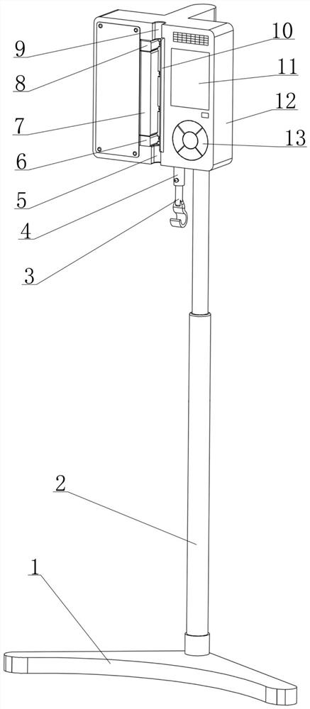
[0044] see figure 1 , 2 10, a medical clinical drainage control device disclosed in this embodiment is composed of a support assembly, a weighted suspension assembly 4, a drainage adjustment assembly, a controller, and a power supply assembly 14;

[0045] Among them, see figure 1 , 2 As shown, the support assembly is composed of a base 1, a column 2 and a mounting plate 12, the column 2 is supported by the base 1 and extends vertically, the mounting plate 12 is supported by the column 2 and is located above the base 1, and at the same time Located on the front side of the column 2; the placement plate 12 is used to provide support and installation space for other components;

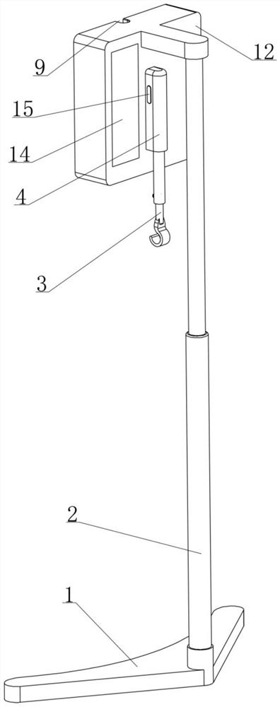
[0046] Among them, see figure 2 , 9 , 10, the weight-based suspension assembly 4 is supported by a mounting plate 12, with a built-in load cell 15 and a hanging part 3 at the lower end; it is used to provide the only support for the drainage bag 22 and make the drainage bag 22 hangs below the plac...

Embodiment 2

[0092] see figure 2 , 9 As shown, in the medical clinical drainage control device disclosed in Embodiment 1, it has been clarified that the accuracy of the weighing signal output by the load cell 15 is greatly affected by whether the medical clinical drainage control device is placed horizontally; Although the difference can be solved by laying objects under the base 1, the operation is cumbersome, time-consuming and labor-intensive. For this reason, this embodiment is based on the structure of the medical clinical drainage control device disclosed in the embodiment. With the following improvements:

[0093] like Figure 16 , 17 As shown, the rear side of the placement plate 12 is fixed with a first rotating shaft 44 extending horizontally backward, and a swing seat 43 is fixed by the first rotating shaft 44 to swing left and right in a small range; the weighted suspension assembly 4 The upper end is connected with the swing seat 43 through the second rotating shaft 42 so...

Embodiment 3

[0099] see Figure 9 As shown, drainage is a commonly used clinical medical method at present, and the clinical drainage process is mostly carried out in the ward, and the medical clinical drainage control device needs to be frequently moved back and forth between the ward and the ward, and between the ward and the instrument room; When the aforementioned medical clinical drainage control device is in clinical use, the whole device can be said to be provided with stable support by the base 1. The base 1 is bound to be large and heavy, and the overall movement of the medical clinical drainage control device is laborious and affected by the base 1. The overall volume of the drainage control device is large, and it takes up a large space when used, and the flexibility is poor;

[0100] Generally speaking, the infusion stand is a necessary medical device in the ward. Its structure is relatively simple and it takes up less space. For example, the medical clinical drainage control d...


PUM


Abstract

The invention relates to the field of medical instruments, and discloses a medical clinical drainage control device. The device is composed of a support assembly and a weighing type suspension supportassembly, a drainage adjusting assembly, a controller and a power supply assembly which are supported by the support assembly; the weighing type suspension support assembly can provide support for adrainage bag and feed back a weight signal to the controller; and the controller can adjust and control the working state of the drainage adjusting assembly on the basis of the obtained weight signal,a preset drainage mode and a preset drainage parameter, so that the drainage adjusting assembly extrudes the drainage tube in different modes to achieve operation and control of negative pressure drainage and normal pressure drainage. The medical clinical drainage control device adopts intelligent design, can achieve automatic control over timing drainage, quantitative drainage and constant-speeddrainage when used in cooperation with an existing conventional drainage assembly, improves the safety and stability of drainage operation, has two drainage modes of normal-pressure drainage and negative-pressure drainage, can meet most of clinical drainage requirements, and has wide application prospects clinically.

Description

[0001] The present invention is a divisional application of the invention patent application with application number 2018111350204 submitted on September 28, 2018. technical field [0002] The invention relates to the technical field of medical devices, in particular to a medical clinical drainage control device which can automatically regulate various drainage techniques in clinical practice. Background technique [0003] Under normal conditions, there is a small amount of fluid in the thoracic cavity and abdominal cavity of the human body, which can lubricate the organs in the cavity. If the amount of fluid in the cavity increases beyond the normal physiological range under pathological conditions, it will become a disease, such as pleural effusion and ascites. There are many causes of peritoneal effusion and pleural effusion, which are very common clinical diseases. Although peritoneal effusion and pleural effusion are only one symptom, a large amount of peritoneal effusi...

Claims


Application Information

Patent Timeline
Patent Type & Authority Applications(China)
IPC IPC(8): A61M1/00
CPCA61M1/0023A61M2205/3334A61M1/74
Inventor 王才丰
Owner 德州飚丰信息技术有限公司
Why Eureka
Try Eureka