Centrifugal ventilating vane with slotted structure

A centrifugal fan and ventilator technology, applied in mechanical equipment, machines/engines, liquid fuel engines, etc., can solve the problems of complex impeller channel flow, poor fan performance, large vortex noise, etc., to widen the efficient operation area, improve Efficiency and pressure ratio, the effect of improving flow field conditions

Active Publication Date: 2020-11-17
TAIZHOU UNIV
View PDF8 Cites 1 Cited by
  • Summary
  • Abstract
  • Description
  • Claims
  • Application Information

AI Technical Summary

Problems solved by technology

The flow in the impeller channel of the centrifugal fan is very complicated, and the flow separation phenomenon is easy to occur in the impeller channel under the condition of lower than the rated flow rate, especially the separation phenomenon near the suction surface of the blade trailing edge is serious, which brings adverse effects on the performance of the fan. Influence, the efficiency will drop, and may generate large vortex noise

Method used


Image

  • Centrifugal ventilating vane with slotted structure
  • Centrifugal ventilating vane with slotted structure
  • Centrifugal ventilating vane with slotted structure

Examples


Embodiment Construction

[0018] The present invention will be further described below in conjunction with the accompanying drawings and embodiments.

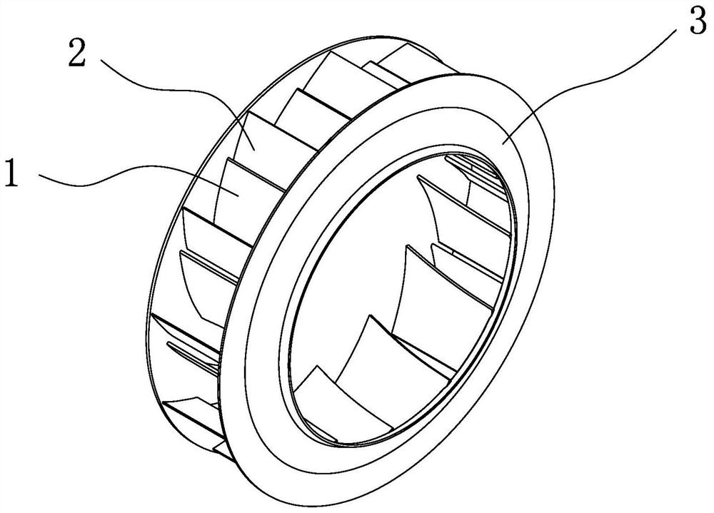
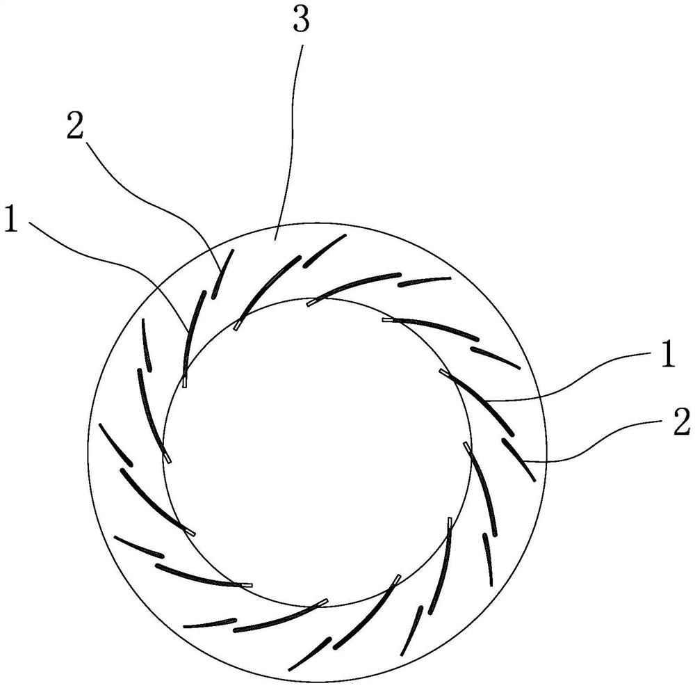
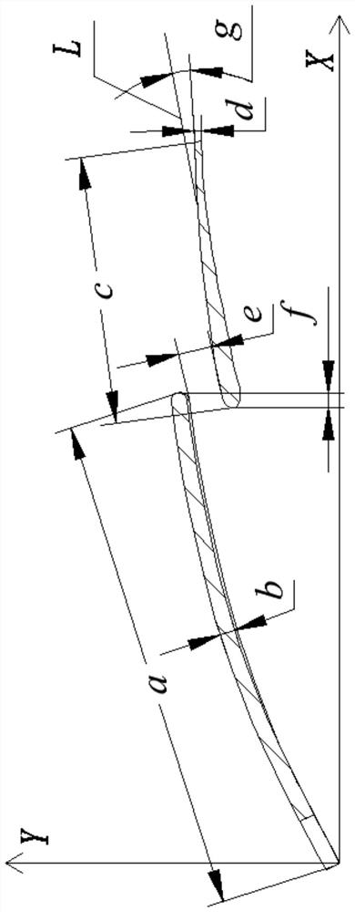
[0019] Such as Figure 1 and Figure II As shown, the embodiment of the present invention includes several groups of blade assemblies located in the impeller 3 of the ventilator, each group of blade assemblies is arranged in an annular array at the center of the impeller 3, and each group of blade assemblies includes a long blade 1 and a short blade assembly. Blade 2. The diameter of the impeller in this embodiment is D, and other main parameters are as Figure three As shown, it includes the length a and thickness b of the long blade, the length c of the short blade and the thickness d of the trailing edge, the gap width e, and the overlapping length f of the long and short blades. The included angle formed by the outlet tangent is the deflection angle g of the short blade, and the blade outlet is at the trailing edge of the short blade. This embod...


PUM


Abstract

The invention discloses a centrifugal ventilating vane with a slot. An original model vane is optimized by adopting a slotting technology method; a long vane part of the slotted vane is in a flat plate shape; a short vane part of the slotted vane is in a wing shape; the slotted vane has main parameters including the length, width and thickness of the long vane, the length, width and thickness of the short vane, the slit width, the overlapping length of the long vane and the short vane, and a deflection angle of the short vane; and the slit width, the overlapping length of the long vane and theshort vane and the deflection angle of the short vane have great influence on the performance of a fan. When the short vane reverses the angle, jet flow is formed at a slit, so that a boundary layeron the suction surface side of the short vane is thinned, and separation is inhibited. By means of the slotting technology, the efficiency and the pressure ratio can be improved, the efficient operation area of the fan can be widened, the noise can be lowered, and the phenomenon that a dust-containing and moisture-containing airflow adheres to and abrades the vane in the conveying process can be improved.

Description

technical field [0001] The invention belongs to the field of fan equipment and relates to a centrifugal fan, in particular to a centrifugal fan blade with a slit structure. Background technique [0002] Impeller machinery occupies an important position in the national economy, especially in power, energy, chemical industry, aviation, metallurgy and other professional fields and has been widely used. Turbo machinery also consumes a lot of electricity while working. The energy problem is also a prominent problem in my country's economic development, which is mainly manifested in the low energy utilization rate. There are many reasons for this problem, and one of the main factors is the efficiency of the equipment itself. In response to the increasingly tense energy situation, turbomachinery with high design efficiency, wide range of working conditions, and good operating safety has become the unremitting goal of workers in related fields. With the expansion of modern industr...

Claims


Application Information

Patent Timeline
Patent Type & Authority Applications(China)
IPC IPC(8): F04D29/28F04D29/30F04D29/66
CPCF04D29/281F04D29/30F04D29/666F04D29/667
Inventor 李哲弘叶信学邢慧芬罗平刘文飞陈子云王正初
Owner TAIZHOU UNIV
Why Eureka
Try Eureka