Optical system, image capturing module and electronic device

An optical system and module technology, applied in the field of photography, can solve problems such as the need to improve the luminous flux

Pending Publication Date: 2021-02-19
TIANJIN OFILM OPTO ELECTRONICS CO LTD
View PDF0 Cites 2 Cited by
  • Summary
  • Abstract
  • Description
  • Claims
  • Application Information

AI Technical Summary

Problems solved by technology

However, in order to achieve a clear imaging effect in a weak light environment, the luminous flux of the traditional infrared detection lens needs to be improved

Method used


Image

  • Optical system, image capturing module and electronic device
  • Optical system, image capturing module and electronic device
  • Optical system, image capturing module and electronic device

Examples


no. 1 example

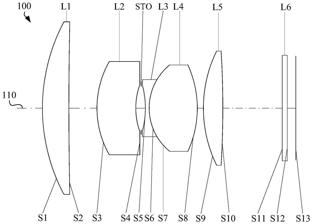
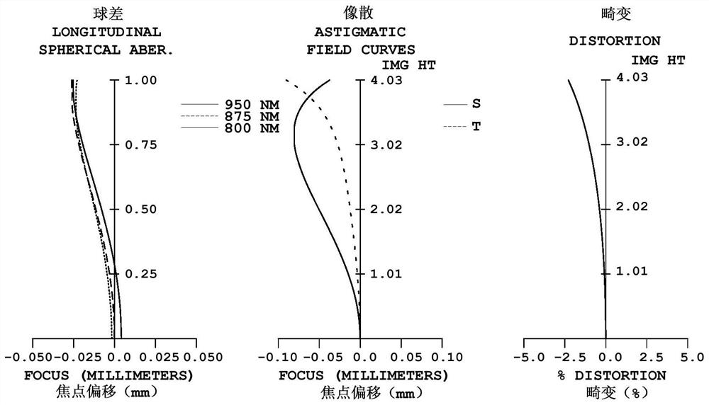
[0076] See figure 1 with figure 2 , figure 1 It is a schematic diagram of the optical system 100 in the first embodiment. The optical system 100 includes a first lens L1 with a positive refractive power, a second lens L2 with a negative refractive power, an aperture STO, and a lens with a negative refractive power from the object side to the image side. A third lens L3 with a refractive power, a fourth lens L4 with a positive refractive power, and a fifth lens L5 with a positive refractive power. figure 2 From left to right are the graphs of spherical aberration, astigmatism and distortion of the optical system 100 in the first embodiment, where the reference wavelength of the astigmatism graph and distortion graph is 875nm, and other embodiments are the same.

[0077] The object side S1 of the first lens L1 is a convex surface at the paraxial position;

[0078] The image side S2 of the first lens L1 is concave at the paraxial position;

[0079] The object side S3 of the...

no. 2 example

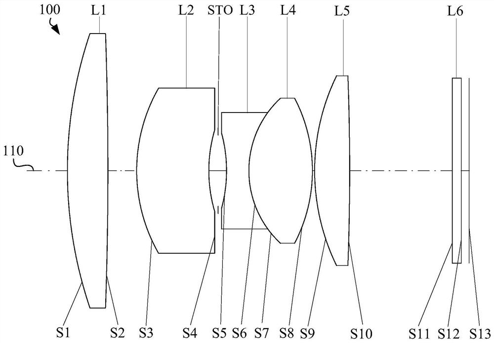
[0107] See image 3 with Figure 4 , image 3 It is a schematic diagram of the optical system 100 in the second embodiment. The optical system 100 includes a first lens L1 with positive refractive power, a second lens L2 with positive refractive power, a diaphragm STO, and a lens with negative refractive power from the object side to the image side. A third lens L3 with a refractive power, a fourth lens L4 with a positive refractive power, and a fifth lens L5 with a positive refractive power. Figure 4 From left to right are the graphs of spherical aberration, astigmatism and distortion of the optical system 100 in the first embodiment.

[0108] The object side S1 of the first lens L1 is a convex surface at the paraxial position;

[0109] The image side S2 of the first lens L1 is a convex surface at the paraxial position;

[0110] The object side S3 of the second lens L2 is a convex surface at the paraxial position;

[0111] The image side S4 of the second lens L2 is conc...

no. 3 example

[0128] See Figure 5 with Image 6 , Figure 5 It is a schematic diagram of the optical system 100 in the third embodiment. The optical system 100 includes a first lens L1 with a positive refractive power, a second lens L2 with a negative refractive power, an aperture STO, and a lens with a negative refractive power from the object side to the image side. A third lens L3 with a refractive power, a fourth lens L4 with a positive refractive power, and a fifth lens L5 with a positive refractive power. Image 6 From left to right are the graphs of spherical aberration, astigmatism and distortion of the optical system 100 in the second embodiment.

[0129] The object side S1 of the first lens L1 is a convex surface at the paraxial position;

[0130] The image side S2 of the first lens L1 is a plane at the paraxial position;

[0131] The object side S3 of the second lens L2 is a convex surface at the paraxial position;

[0132] The image side S4 of the second lens L2 is concave...


PUM


Abstract

The invention relates to an optical system, an image capturing module and an electronic device. The optical system comprises the following components in an order from an object side to an image side:a first lens element with positive refractive power; a second lens element with refractive power; a third lens element with negative refractive power; a fourth lens element with positive refractive power, wherein the third lens element is cemented to the fourth lens element; and a fifth lens element with positive refractive power. The optical system satisfies the conditional expression that FNO issmaller than or equal to 1.9, wherein FNO is the number of apertures of the optical system. According to the optical system, when the conditional expression is met, the large-aperture characteristicof the optical system can be realized, so the luminous flux of the optical system is improved.

Description

technical field [0001] The invention relates to the field of imaging, in particular to an optical system, an imaging module and electronic equipment. Background technique [0002] Infrared detection lenses are widely used in military equipment, security monitoring, three-dimensional space measurement, etc. Luminous flux is an important performance index of the infrared detection lens. It is required that the infrared detection lens can still collect the infrared light reflected by the object to a large extent in a weak light environment, so as to fully obtain the information of the target object. However, in order to achieve a clear imaging effect in a weak light environment, the luminous flux of the traditional infrared detection lens needs to be improved. Contents of the invention [0003] Based on this, it is necessary to provide an optical system, an imaging module and electronic equipment to increase the luminous flux of the optical system. [0004] An optical syste...

Claims


Application Information

Patent Timeline
IPC IPC(8): G02B13/00G02B13/02G02B13/14G02B13/18G02B13/22
CPCG02B13/0045G02B13/006G02B13/02G02B13/14G02B13/18G02B13/22
Inventor 杨懿刘秀蔡雄宇
Owner TIANJIN OFILM OPTO ELECTRONICS CO LTD
Why Eureka
Try Eureka