Feeding device for micromotor rotor winding machine

A winding machine and micro-motor technology, which is applied in the direction of electromechanical devices, workpiece clamping devices, manufacturing motor generators, etc., can solve the problems of easy deviation and low feeding efficiency

Active Publication Date: 2021-04-09
温岭市新纪元微电机厂(普通合伙)
View PDF9 Cites 2 Cited by
  • Summary
  • Abstract
  • Description
  • Claims
  • Application Information

AI Technical Summary

Problems solved by technology

[0004] In view of the above-mentioned related technologies, the inventor believes that in the process of loading the rotor of the micro-motor, it is easy to cause deviations due to the need for people to position, and the overall feeding efficiency is low

Method used


Image

  • Feeding device for micromotor rotor winding machine
  • Feeding device for micromotor rotor winding machine
  • Feeding device for micromotor rotor winding machine

Examples


Embodiment Construction

[0035]Contraction belowFigure 1-4Further detailed description of the present application.

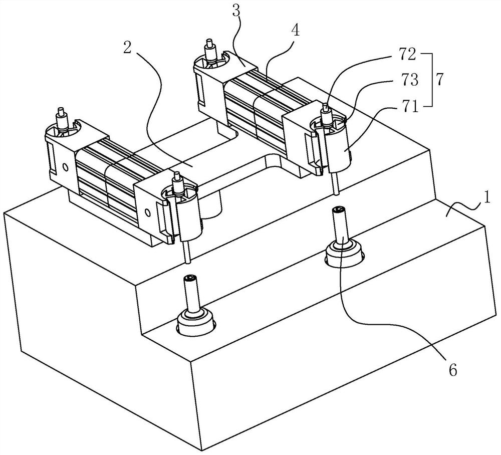
[0036]Such asfigure 1 As shown, the micromotor rotor 7 mainly includes a rotor core 71 and a rotor shaft 72 through the center of the rotor core 71, and the rotor core 71 side wall is provided with several winding grooves 73, such as the rotor core 71 circumferential array Three winding grooves 73, by winding machine, a set of winding groups are formed around the copper wire in adjacent two winding grooves 73, and three sets of winding groups are formed in turn around the rotor core 71, thereby completing the micro motor rotor. 7 winding work.

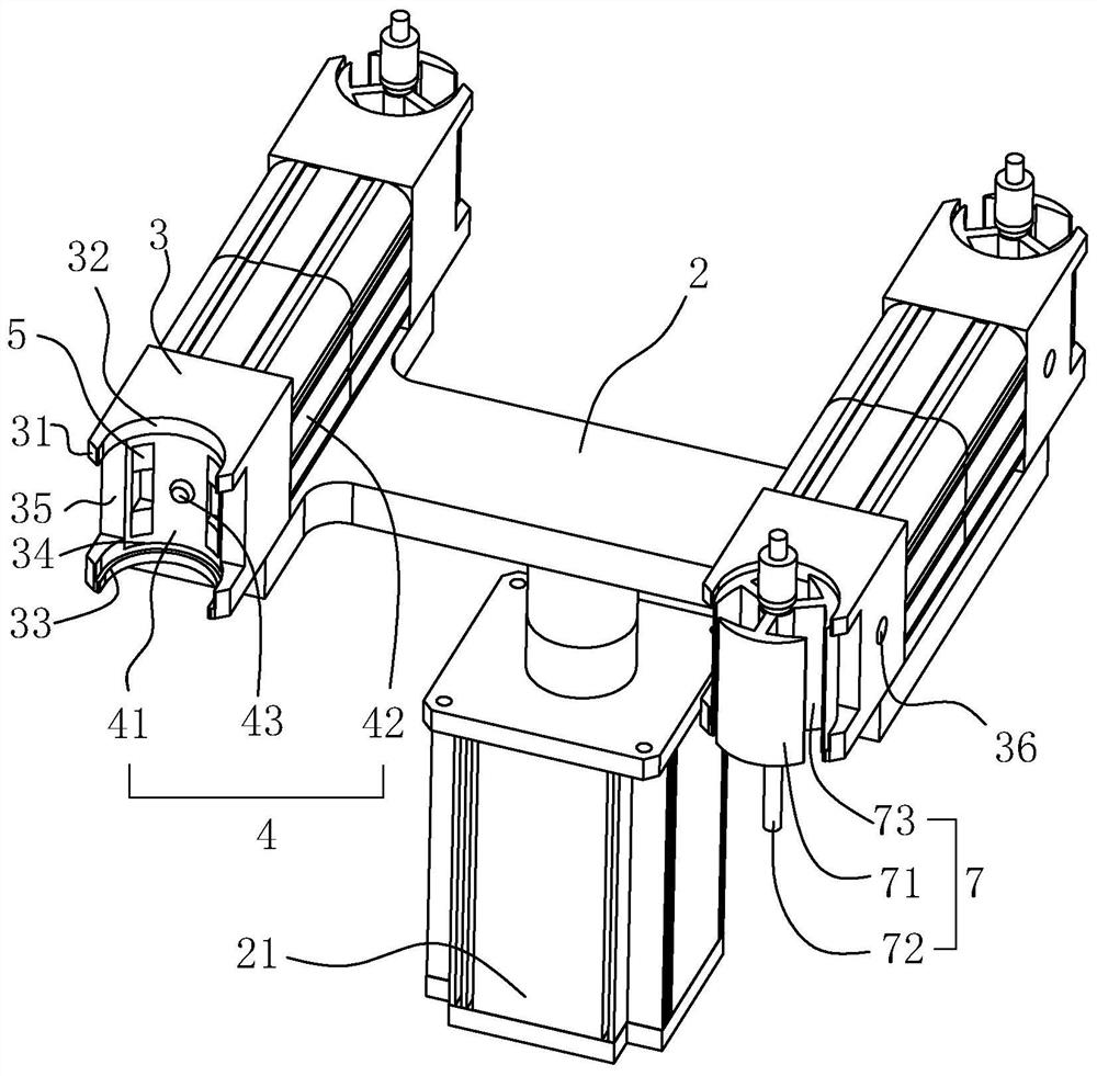
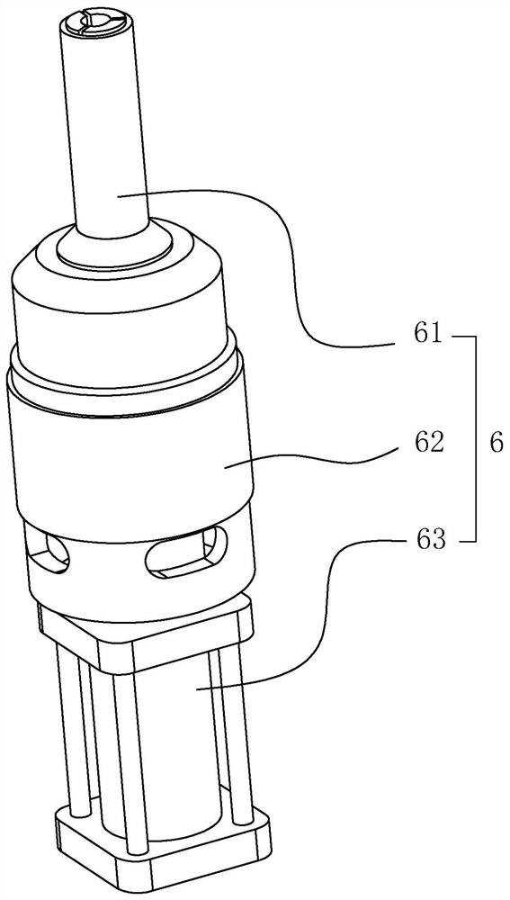
[0037]Such asfigure 1 As shown, the winding machine mainly includes an upper plate 1, a winder head, an amplifier portion, wherein the upper pad 1 is provided with a fixed micromotor rotor 7 and the angle regulator 6 rotating, and when the winding is processed, The microcomputer rotor 7 is fixed to the angle adjuster 6, and the wired head is rely toward the...


PUM


Abstract

The invention relates to the field of micromotor rotor winding machines, and in particular to a feeding device for a micromotor rotor winding machine. The device comprises a feeding table and further comprises a rotating table with the center rotationally connected to the feeding table, a driver for driving the rotating table to rotate is arranged on the feeding table, and rotor limiting heads are symmetrically arranged at the two ends of the rotating table with respect to the rotating center axis. The rotor limiting heads are provided with rotor positioning assemblies, a micromotor rotor can be effectively positioned before being wound, and in the winding process of the micromotor rotor in the rotor limiting head on one side, the micromotor rotor can be taken and placed in the rotor limiting head on the other side, so that the winding positioning accuracy is improved, and the winding efficiency is effectively improved.

Description

Technical field[0001]The present application relates to the field of micro motor rotor winding machines, and more particularly to a sheet device for micro motor rotor winding machine.Background technique[0002]The micromotor rotor mainly includes a rotor core and a rotor shaft through which is at the center of the rotor core, and a plurality of wind grooves are provided in the side wall of the rotor core, and the wound groove is wound around the copper wire.[0003]In order to improve the processing efficiency of the micromotor rotor, the rotor winding machine is currently prepared for processing, such as the application publication number as the rotor winding machine disclosed in CN105811689A, wherein the winding machine mainly includes a plate, a winder head, The discharge portion, wherein the upper pad is provided with a fixed micromotor rotor and the angle regulator rotating. When the wound is processed, people fix the microcomputer rotor to the angle adjuster, and the winder head ...

Claims


Application Information

Patent Timeline
Patent Type & Authority Applications(China)
IPC IPC(8): H02K15/09B25B11/00H01F41/096
CPCB25B11/00H02K15/09H01F41/096
Inventor 洪良传陈鑫哲陈方俊
Owner 温岭市新纪元微电机厂(普通合伙)
Why Eureka
Try Eureka