A closed power distribution cabinet

A power distribution cabinet and closed technology, which is applied in the field of closed power distribution cabinets, can solve the problems of power distribution cabinet damage, high heat, and poor heat dissipation capacity of the heat dissipation part, so as to increase the area, increase the heat dissipation area, and improve the strain capacity Effect

Active Publication Date: 2022-07-22
福建森源电力设备有限公司
View PDF4 Cites 1 Cited by
  • Summary
  • Abstract
  • Description
  • Claims
  • Application Information

AI Technical Summary

Problems solved by technology

[0004] Aiming at the deficiencies of the prior art, the present invention provides a closed power distribution cabinet, which solves the problem that in order to prevent dust from entering the inside of the cabinet, the heat dissipation of the heat dissipation part of the closed power distribution cabinet is often not very good, which may easily cause the cabinet to When working, high heat is generated, causing partial damage to the power distribution cabinet

Method used


Image

  • A closed power distribution cabinet
  • A closed power distribution cabinet
  • A closed power distribution cabinet

Examples


Embodiment 1

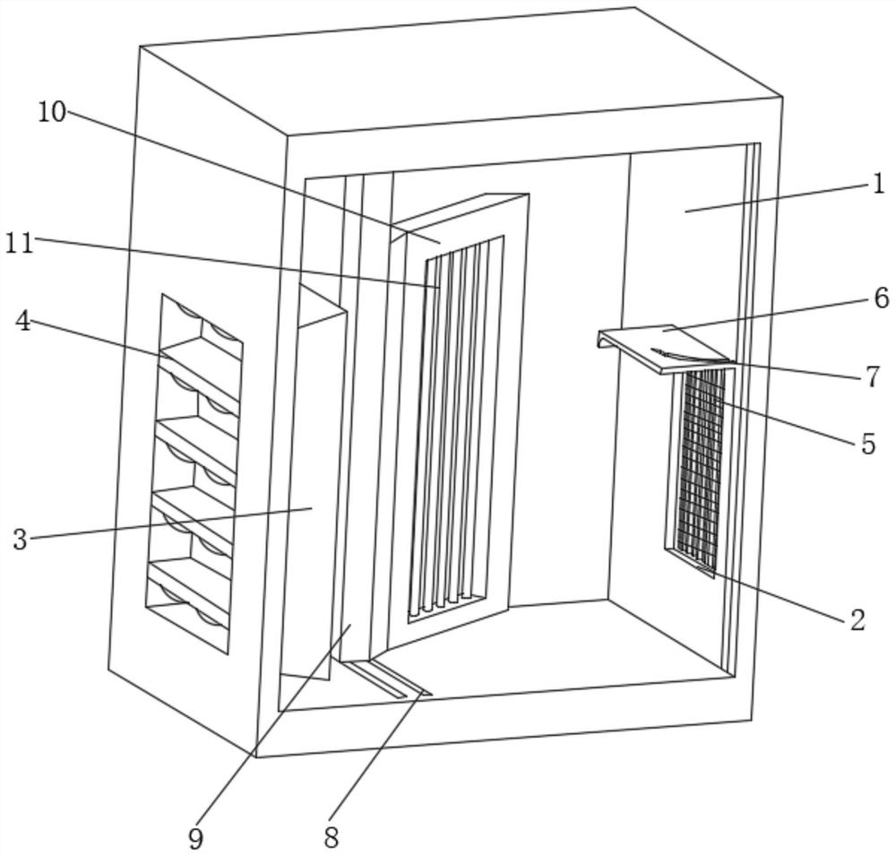
[0029] see Figure 1-2 , the present invention provides a technical solution: a closed power distribution cabinet, comprising a box body 1, windows 2 are opened on the left and right sides of the outer surface of the box body 1, and a conical frame is fixedly connected to the inner surface of the left window 2 3. The inner surface of the conical frame 3 is fixedly connected with a dust removal mechanism 4, the inner surface of the right window 2 is rotatably connected with a retractable mechanism 5, and the inner wall of the box body 1 and located above the right window 2 is fixedly connected with a fixed plate 6. The outer surface of the fixed plate 6 is provided with an arc-shaped groove 7, and the bottom of the inner surface of the box body 1 is provided with a sliding groove 8. The inner surface of the sliding groove 8 is slidably connected with a sliding column 9, and the outer surface of the sliding column 9 is connected to the box body. The inner surface of 1 is slidabl...

Embodiment 2

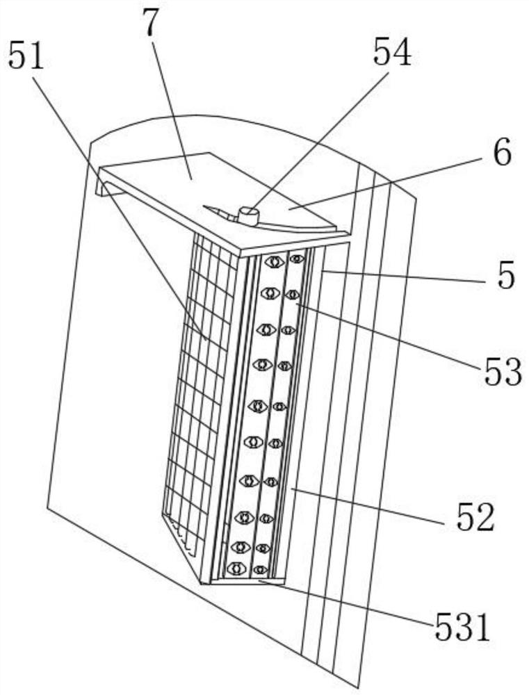
[0031] see figure 2 , the present invention provides a technical solution: the retractable mechanism 5 includes a heat dissipation window 51, the right rear of the heat dissipation window 51 is rotatably connected to the inner surface of the right window 2, and the front of the heat dissipation window 51 is rotatably connected with a side window 52, ​​and the side window The outer surface of 52 is rotatably connected with the inner surface of the right window 2, the inner surface of the side window 52 is provided with a connecting mechanism 53, and the top of the heat dissipation window 51 is fixedly connected with a sliding block 54 on the side close to the side window 52. The sliding block The outer surface of 54 is slidably connected with the inner surface of the arc groove 7 . When the heat dissipation requirement is not large, the side window 52 can be retracted to prevent the entry of dust.

Embodiment 3

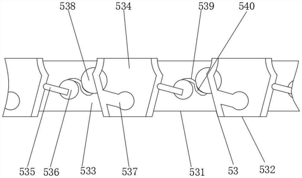
[0033] see Figure 3-4, the present invention provides a technical solution: the connecting mechanism 53 includes a telescopic rod 531, the left and right ends of the telescopic rod 531 are respectively connected to the outer surface of the heat dissipation window 51 and the inner surface of the right window 2 in rotation, and the outer surface of the telescopic rod 531 is fixed. A dust-proof plate 532 is connected, and the outer surface of the dust-proof plate 532 is respectively provided with a first vertical groove 533 and a second vertical groove 534 .

[0034] The inner surface of the first vertical slot 533 is rotatably connected with a vertical plate 535, the outer surface of the vertical plate 535 is rotatably connected with an upper rotating rod 536, the outer surface of the second vertical groove 534 is rotatably connected with a lower rotating rod 538, and the second vertical groove 534 A card slot 537 is opened on the inner surface of the card slot 537 , and the in...


PUM


Abstract

The invention discloses a closed power distribution cabinet, which relates to the technical field of power distribution cabinets. The closed power distribution cabinet includes a box body, windows are opened on the left and right sides of the outer surface of the box, a tapered frame is fixedly connected to the inner surface of the left window, and a dust removal mechanism is fixedly connected to the inner surface of the tapered frame. The inner surface of the right window is rotatably connected with a retractable mechanism, and the inner wall of the box body is fixedly connected to the upper side of the right window. When the heat inside the box is large, the retractable mechanism is opened to increase the heat dissipation area of ​​the window, so that the heat dissipates faster, and the dust removal mechanism is heated to work, spraying water mist, and water droplets formed by the accumulation of water mist. The dust flows out of the box along the window, the mechanism can maximize the area of ​​the heat dissipation window while removing dust, and improve the safety of the closed power distribution cabinet.

Description

technical field [0001] The invention relates to the technical field of power distribution cabinets, in particular to a closed power distribution cabinet. Background technique [0002] Power distribution cabinets are divided into power distribution cabinets, lighting distribution cabinets, and metering cabinets, which are the final equipment of the power distribution system. Power distribution cabinet is a general term for motor control center. The power distribution cabinet is used in situations where the load is relatively scattered and there are few circuits; the motor control center is used in the situations where the load is concentrated and there are many circuits. They distribute the electrical energy of a certain circuit of the upper-level power distribution equipment to the nearest load. This class of equipment shall provide protection, monitoring and control of the load. [0003] Because some power distribution cabinets are in processing workshops, casting, forgi...

Claims


Application Information

Patent Timeline
Patent Type & Authority Patents(China)
IPC IPC(8): H02B1/28H02B1/56H02B1/30
CPCH02B1/28H02B1/565H02B1/30
Inventor 杨志恒
Owner 福建森源电力设备有限公司
Why Eureka
Try Eureka