Medical tracheostomy cannula

A technology of tracheotomy tube and trachea, which is applied in the field of medical equipment and can solve the problems of inconvenient use, low operation safety and high cost

Pending Publication Date: 2021-06-08
安徽医科大学第四附属医院
View PDF0 Cites 0 Cited by
  • Summary
  • Abstract
  • Description
  • Claims
  • Application Information

AI Technical Summary

Problems solved by technology

When using an air bag pressure gauge for operation, only one tracheal air bag in the patient's trachea can be adjusted at a time, and due to its high cost, it is impossible for each patient to be equipped with an air bag pressure gauge, which is very inconvenient to use, so most doctors and nurses Personnel generally use a lot of disposable syrin

Method used


Image

  • Medical tracheostomy cannula
  • Medical tracheostomy cannula
  • Medical tracheostomy cannula

Examples


Embodiment 1

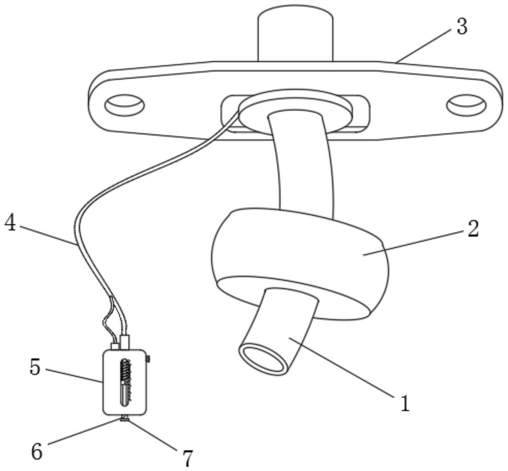
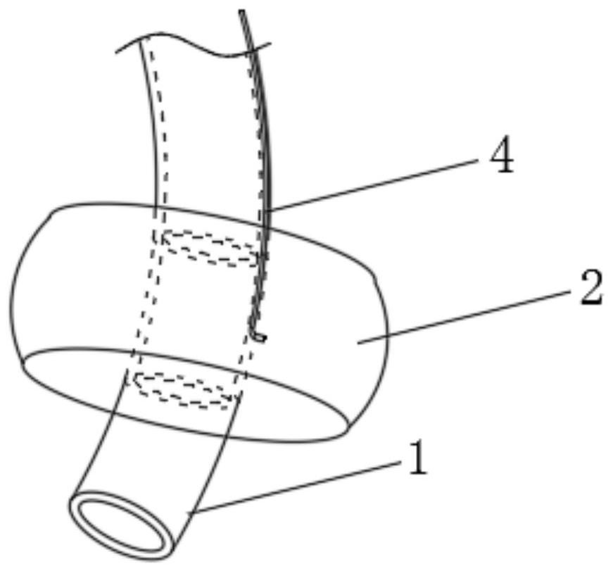
[0031] Such as Figure 1-4 As shown, a medical tracheotomy sleeve includes a main tube 1, a tracheal balloon 2 and a fixed wing 3, the main tube 1 is fixed on the fixed wing 3, and the tracheal balloon 2 is arranged outside the main tube 1 and connected to the main tube 1 wall The inflatable air passages inside are connected, and one end of the inflatable air passage in the pipe wall of the main pipe 1 is connected to the dual-channel air bag tube 4, and one end of the dual-channel air bag pipe 4 is connected to the pressure detection mechanism 5;

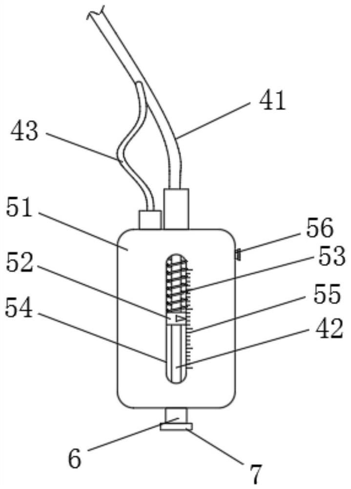
[0032] The pressure detection mechanism 5 includes a detection tube 51, a piston 52, a spring 53, an observation window 54 and a scale mark 55. The piston 52 slides in the detection tube 51 through the spring 53 and is connected to the observation window 54 and the scale on the surface of the detection tube 51. Corresponding to the line 55, the detection tube 51 is provided with an exhaust port 56, and the exhaust port 56 is provid...

Embodiment 2

[0043] Such as Figure 5-8 As shown, one end of the hard tube runs through the detection tube 51 and extends to the front side wall of the detection tube 51. The inflation port 7 is arranged on one side of the hard tube and is connected to the micro pump 10 through the air inlet pipe 12. The air inlet pipe 12 It is connected with the air outlet of the micro pump 10.

[0044] In addition, a fastening bolt 11 can be set against the side of the pump rod on the micro-pump 10 , and the fastening bolt 11 is threadedly connected with the barrel of the micro-pump 10 .

[0045] The embodiment is specifically: when inflating the tracheal airbag 2, the micro-pump 10 can also be used to inflate. The air valve can continuously inflate the inner pipeline 41 and the tracheal airbag 2 through the air intake pipe 12, and because the micro-pump 10 is small in size, it can be inflated multiple times, at best each time is less, avoiding excessive inflation at one time. After being inflated to a...


PUM


Abstract

The invention relates to a medical tracheostomy cannula. The tracheostomy cannula comprises a main tube, a tracheal air bag and a fixed wing, wherein the main tube is fixed on the fixed wing; the tracheal air bag is arranged outside the main tube and communicates with an inflation flow channel in the tube wall of the main tube; one end of the inflation flow channel in the tube wall of the main tube is connected with a double-channel air bag tube; one end of the double-channel air bag tube is connected with a pressure detection mechanism; the pressure detection mechanism comprises a detection tube, a piston, a spring, an observation window and scale marks; the piston slides in the detection tube through the spring and corresponds to the observation window and the scale marks on the surface of the detection tube; and an exhaust port is formed in the detection tube. The double-channel air bag tube is arranged and connected with an inflation structure, the tracheal air bag and the detection tube, so that the tracheal air bag can be inflated, and meanwhile, the air pressure in the tracheal air bag can be detected; and the structure is simple, reading is convenient, accurate inflation can be achieved, and an air bag pressure gauge does not need to be additionally used for pressure detection.

Description

technical field [0001] The invention belongs to the field of medical equipment, and in particular relates to a medical gas cutting sleeve. Background technique [0002] A tracheostomy is an emergency procedure used to relieve shortness of breath caused by an airway obstruction. For respiratory failure caused by retention of lower respiratory tract secretions (such as craniocerebral trauma, thoracoabdominal trauma, polio, etc.), tracheotomy is an important auxiliary treatment method, and the lower respiratory tract secretions can be sucked out through the tracheotomy tube , thereby improving gas exchange in the lungs. In addition, in order to cooperate with the smooth operation of the mouth, pharynx and other parts, the necessary tracheotomy can prevent blood from flowing down into the respiratory tract and obstruct breathing, so that the respiratory tract will be unobstructed during the operation. [0003] The tracheotomy tube is generally composed of a main tube, a trache...

Claims


Application Information

Patent Timeline
IPC IPC(8): A61M16/04
CPCA61M16/0434A61M16/0465A61M16/0497A61M2016/0027A61M2205/3331A61M16/0486
Inventor 姚明孙中武何莹程谦涛吕达平张刚张忠正王玲玲霍佳佳
Owner 安徽医科大学第四附属医院
Why Eureka
Try Eureka