Multifunctional power distribution cabinet

A multi-functional power distribution cabinet and cabinet technology, which is applied in the substation/distribution device shell, electrical components, substation/switch layout details, etc. , The effect of improving the heat dissipation speed and improving the fire fighting ability

Inactive Publication Date: 2021-06-29
胡明
View PDF0 Cites 0 Cited by
  • Summary
  • Abstract
  • Description
  • Claims
  • Application Information

AI Technical Summary

Problems solved by technology

[0003] The power distribution cabinet needs to strictly ensure the normal operation of the internal electrical components to avoid large property losses caused by short circuit fires. The existing fire protection level of the power distribution cabinet is not in place, and the fire protection measures need to be further improved

Method used


Image

  • Multifunctional power distribution cabinet
  • Multifunctional power distribution cabinet
  • Multifunctional power distribution cabinet

Examples


Embodiment 1

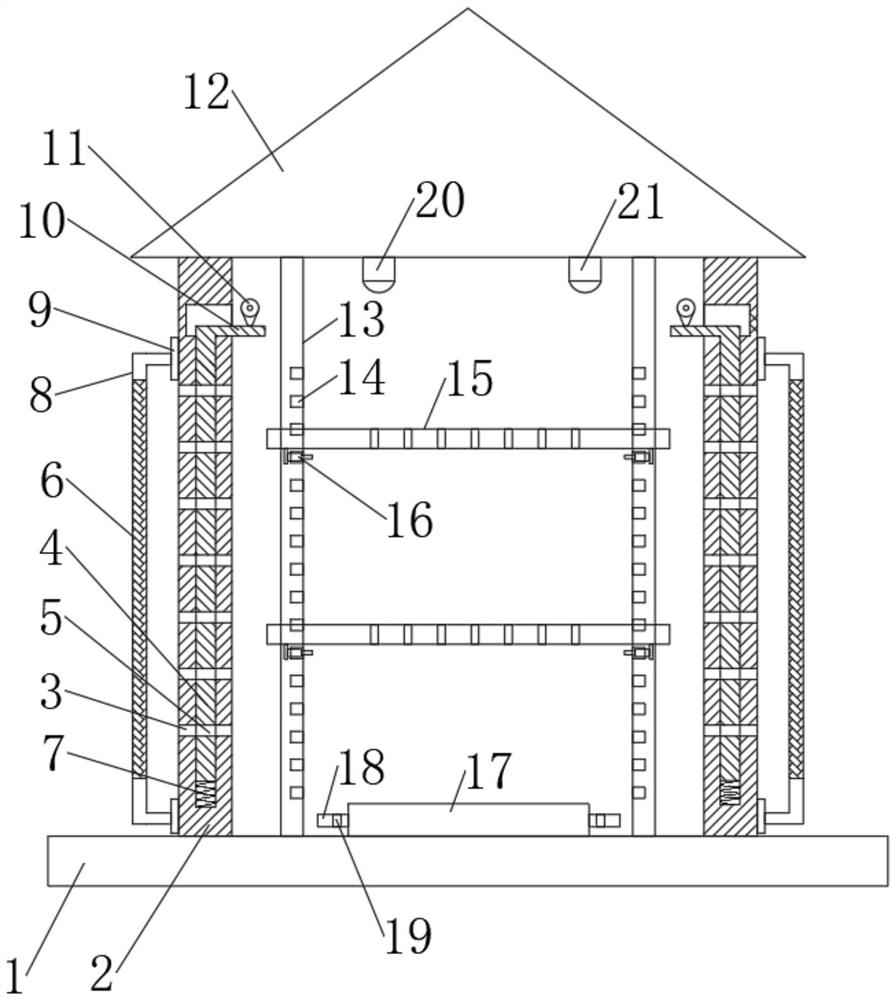
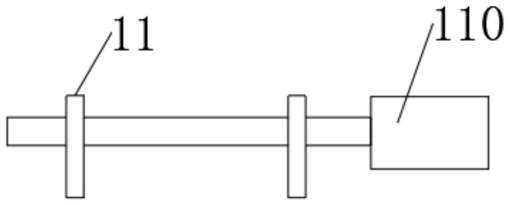
[0026] Such as Figure 1-5 As shown, a multi-functional power distribution cabinet includes a base 1, a cabinet body 2 is arranged on the base 1, first cooling holes 3 are evenly arranged on the sides of the cabinet body 2, and first cooling holes 3 are uniformly arranged on the sides of the cabinet body 2. It is hollow, and the side of the cabinet body 2 is inserted with a sandwich panel 4, and the sandwich panel 4 is uniformly provided with second heat dissipation holes 5, and the first heat dissipation holes 3 and the second heat dissipation holes 5 are adjustable Type installation, the bottom of the sandwich plate 4 is provided with a spring 7, the upper side of the sandwich plate 4 is provided with a right-angle plate 10, the top of the right-angle plate 10 is provided with a cam 11, and the cam 11 is connected with a rotating motor 110 , the interior of the cabinet body 2 is provided with mounting columns 13, the mounting columns 13 are uniformly provided with fixing gro...

Embodiment 2

[0035] This embodiment is a further improvement and limitation of embodiment 1 on the basis of embodiment 1.

[0036] A multifunctional distribution cabinet, including all the components in Embodiment 1, and also includes:

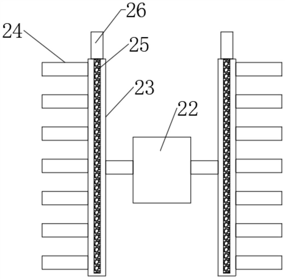
[0037] Further, the cabinet body 2 is provided with a cooling device, and the cooling device includes a cooling fan 22 arranged on the rear side of the cabinet body 2. Concentrating tubes 23 are arranged on both sides of the cooling fan 22, and the focusing tube 23 Branch pipes 24 are evenly arranged on the top.

[0038] Specifically, in order to improve the heat dissipation efficiency inside the cabinet body 2 . By setting the heat dissipation fan 22, combined with the installation of the branch pipe 24 and the concentration pipe 23, the heat dissipation speed is improved.

[0039] Further, a drying rod 25 is arranged in the centralized tube 23 , the drying rod 25 is inserted into the centralized tube 23 , and a handle 26 is provided on the drying rod 2...


PUM


Abstract

The invention discloses a multifunctional power distribution cabinet, relates to the technical field of power distribution cabinets, and mainly solves the problem that fire-fighting measures of an existing power distribution cabinet are not in place. The multifunctional power distribution cabinet comprises a base, wherein a cabinet body is arranged on the base, first heat dissipation holes are evenly formed in the side edge of the cabinet body, the side edge of the cabinet body is hollow, a sandwich plate is inserted into the side edge of the cabinet body, second heat dissipation holes are evenly formed in the sandwich plate, the first heat dissipation holes and the second heat dissipation holes are adjustably formed, aspring is arranged at the bottom part of the sandwich plate, a right-angle plate is arranged on the upper side of the sandwich plate, a cam is arranged above the right-angle plate, the cam is connected with a rotating motor, mounting columns are arranged in the cabinet body, fixing grooves are uniformly formed in the mounting columns, a mounting plate is movably mounted between the mounting columns, a fixing block is arranged at the bottom part of the mounting plate, the fixing block and the bottom part of the mounting plate are rotationally mounted, and the fixing block is matched with the fixing groove.

Description

technical field [0001] The invention relates to the technical field of power distribution cabinets, in particular to a multifunctional power distribution cabinet. Background technique [0002] Power distribution cabinets are referred to as JP cabinets. With the continuous deepening of rural and urban power grid transformation, a large number of power distribution cabinets are used in power lines and distribution stations. Existing power distribution cabinets generally include cabinets, cabinets The front side and the rear side of the car are respectively provided with a front door and a rear door. [0003] The power distribution cabinet needs to strictly ensure the normal operation of the internal electrical components to avoid large property losses caused by short-circuit fires. The existing fire protection level of the power distribution cabinet is not in place, and the fire protection measures need to be further improved. Contents of the invention [0004] The purpose ...

Claims


Application Information

Patent Timeline
IPC IPC(8): H02B1/56H02B1/28A62C3/16A62C31/05A62C37/38
CPCA62C3/16A62C31/05A62C37/38H02B1/28H02B1/565
Inventor 胡明
Owner 胡明
Why Eureka
Try Eureka