Traffic sign board with hollow layout and design method thereof
What is AI technical title?
AI technical title is built by Patsnap AI team. It summarizes the technical point description of the patent document.
A technology of signs and layouts, applied in road signs, traffic signals, design optimization/simulation, etc., can solve the problems of large rod and foundation size, large wind load, etc., and achieve the effect of reducing wind load, quantity and size
Pending Publication Date: 2021-07-23
SHANGHAI URBAN CONSTR DESIGN RES INST GRP CO LTD
View PDF0 Cites 0 Cited by
Summary
Abstract
Description
Claims
Application Information
AI Technical Summary
This helps you quickly interpret patents by identifying the three key elements:
Problems solved by technology
Method used
Benefits of technology
Problems solved by technology
The huge layout receives a large wind load. According to the structural calculation, the size of the rods and the foundation is relatively large
Method used
Image
Click on the blue label to locate the original text in one second.
Reading with bidirectional positioning of images and text.
Examples
Embodiment 1
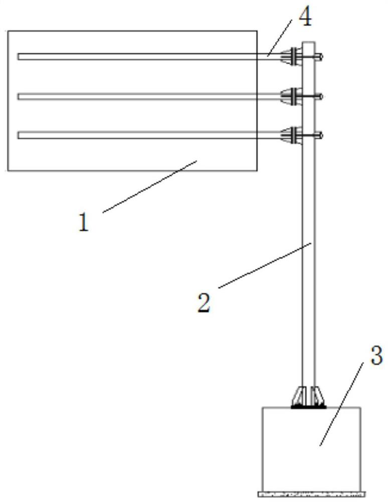
[0093] Such as figure 1 and Figure 3 to Figure 5 As shown, the traffic sign board with a hollow layout includes a sign board main body 1 and a column 2; the lower end of the column 2 and the column foot 3 are connected by a flange;
[0094] Wherein, the main body 1 of the signboard is provided with a hollow.
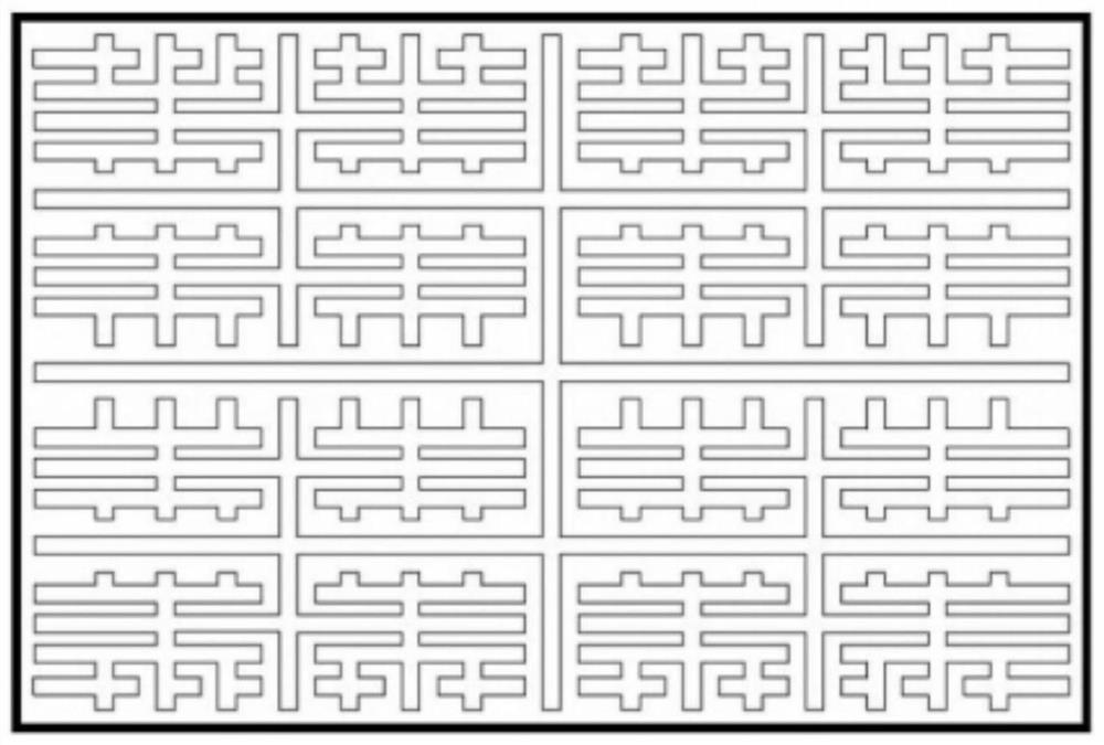
[0095] Such as image 3 As shown, in some embodiments, the hollow is in the shape of a stroke, that is, a through hole that occupies more than 150% of the main body of the signboard and is completely connected;
[0096] The hollowing out divides the main body 1 of the signboard into two plates which are connected into one body through a fixed connection.
[0097] In some embodiments, the fixed connection is welding.
[0098] Such as Figure 4 As shown, in some embodiments, the hollowing includes more than two through holes penetrating through both sides of the main body 1 of the signboard.
[0099] In some embodiments, the through holes are circular holes, polygon...
Embodiment 2
[0172] Take 50% of the hollowness as an example for calculation.
[0173] 1) Calculation of wind load
[0174] ① Sign wind load
[0175] f wb =1.04×1.39A 标 kN=1.45A 标 kN=9.135kN
[0176] ② Column wind load
[0177] f wp =0.693×1.39A 柱 kN=0.963A 柱 kN = 2.754kN
[0178] ③ Wind load on exposed beams
[0179] f wh =0.693×1.39A 梁 kN=0.963A 梁 kN = 0.202kN
[0180] 2) Calculation of 3F rod mark member
[0181] The specification of the column of the 3F pole sign is D325-12mm, the height is 8800mm, the material is Q355B, and the density is 78.5kN / m3. Alloy plate, the mass per unit area of sign plate is 13.26kg / ㎡.
[0182] Logo layout gravity: G 1 =A*W 1 *g*1.1=0.901(KN);
[0183] Beam layout gravity: G 2 ==5.054(KN);
[0184] Column Gravity: G 3 =8.787(KN).
[0185] The total gravity of the upper structure of the sign is G=G 1 +G 2 +G 3 = 14.742 (KN).
[0186] 3) Design and calculation of the beam
[0187] Since the materials and specifications of the thre...
PUM
Abstract
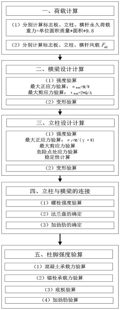
The invention discloses a traffic sign board with a hollow layout and a design method thereof. The traffic sign board comprises a sign board body and a stand column. The lower end of the stand column is connected with the column foot through a flange plate. The signboard body and the stand column are connected through a plurality of cross beams. The signboard main body is provided with a hollow part. The design method comprises the steps of load calculation, design calculation of the cross beams, design calculation of the stand column, connection of the stand column and the cross beams and checking calculation of the strength of the column base. The number and the size of the rod pieces and the foundations can be effectively reduced, the wind load of the sign is effectively reduced, and the traffic sign board and the method can be applied to the rod pieces and the foundations of roads and squares of various grades.
Description
technical field [0001] The invention relates to the technical field of traffic sign board manufacturing, in particular to a traffic sign board with a hollowed-out layout and a design method thereof. Background technique [0002] With the increasing complexity of the road trafficsystem, people's requirements for the convenience of traffic travel are increasing, so the demand for the perfect layout of traffic signs is increasing. [0003] The size of the traffic layout is based on the design speed and the number of fonts, and the combination of words and signs according to certain rules. Usually, the guide signs in the city need to display more content, and the layout signs are larger. Usually the layout of guide signs is several square meters to tens of square meters. The huge layout is subject to large wind loads, and according to structural calculations, the dimensions of the rods and foundations are relatively large. [0004] Therefore, how to reduce the size of rods a...
Claims
Application Information
Patent Timeline
Application Date:The date an application was filed.
Publication Date:The date a patent or application was officially published.
First Publication Date:The earliest publication date of a patent with the same application number.
Issue Date:Publication date of the patent grant document.
PCT Entry Date:The Entry date of PCT National Phase.
Estimated Expiry Date:The statutory expiry date of a patent right according to the Patent Law, and it is the longest term of protection that the patent right can achieve without the termination of the patent right due to other reasons(Term extension factor has been taken into account ).
Invalid Date:Actual expiry date is based on effective date or publication date of legal transaction data of invalid patent.
IPC IPC(8): E01F9/60G06F30/17G06F30/20G09F7/00
CPCE01F9/60G09F7/002G06F30/17G06F30/20G06F2119/14
Inventor张震山张捷胡丹秦雯王春闫兴非王晓婧张涛曹倩云
OwnerSHANGHAI URBAN CONSTR DESIGN RES INST GRP CO LTD

