
Supporting device for TBM end well excavating equipment for subway construction
A technology for excavating equipment and supporting devices, which is applied in the field of supporting devices for excavating equipment used in TBM end wells for subway construction, can solve problems such as poor stability and safety, improve construction efficiency, ensure support balance and stability, and realize fixed The effect of stability
- Summary
- Abstract
- Description
- Claims
- Application Information
AI Technical Summary
Problems solved by technology
Method used
Image

Examples
Embodiment 1
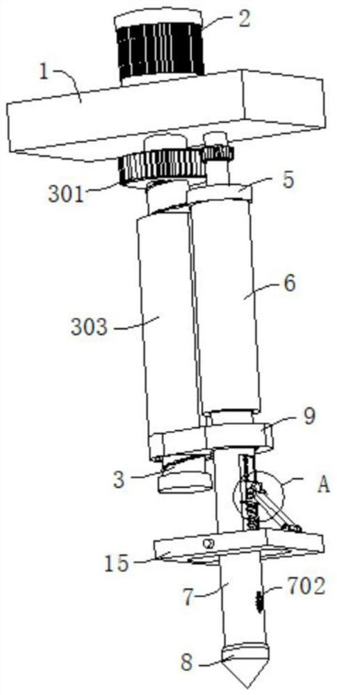
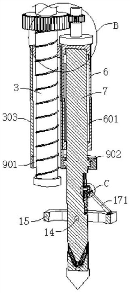
[0036] refer to figure 1 , image 3 , Figure 4 with Image 6, a support device for TBM end well excavation equipment for subway construction, including a mounting plate 1, a first motor 2 is connected to the top of the mounting plate 1, and a rotating shaft is connected to the output end of the first motor 2, and the rotating shaft is far away from the first motor 2 One end passes through the mounting plate 1 and is connected with the first screw rod 3. The outer wall of the first screw rod 3 is connected with a large gear 301. The bottom of the mounting plate 1 is connected with the rotating rod 4 through the bearing rotation. The outer wall of the rotating rod 4 is connected with the large gear 301. Engaged pinion 401, the end of the rotating rod 4 far away from the mounting plate 1 is connected with a fixed plate 5, the outer wall of the fixed plate 5 is connected with a fixed tube 6, the inside of the fixed tube 6 is slidingly connected with a movable rod 7, and the bot...
Embodiment 2
[0042] Such as Figure 1-5 Shown, this embodiment is basically the same as embodiment 1, with reference to figure 1 , image 3 , Figure 4 , Image 6 , Figure 7 , Figure 8 , Figure 9 with Figure 10 , a support device for TBM end well excavation equipment for subway construction, which is basically the same as Embodiment 1, furthermore, a cavity is excavated in the movable rod 7, and a micromotor 10 is connected to the bottom wall of the cavity, and the micromotor 10 The output end of the rotating shaft 11 is connected with a rotating shaft 11, and the end of the rotating shaft 11 away from the micro motor 10 is connected with a transmission gear 111, the inner wall of the cavity is connected with a second screw 12 for rotation, and the outer wall of the second screw 12 is connected with a secondary screw meshing with the transmission gear 111. The movable gear 121 and the second sleeve 122 are threadedly connected to the outer wall of the second screw rod 12 , the s...
Embodiment 3
[0047] refer to Figure 1-9 , a support device for TBM end well excavation equipment for subway construction, which is basically the same as embodiment 2, and furthermore, the movable rod 7 is fixedly connected with a fixed rod 14, and the outer wall of the fixed rod 14 is rotatably connected with a backing plate 15.
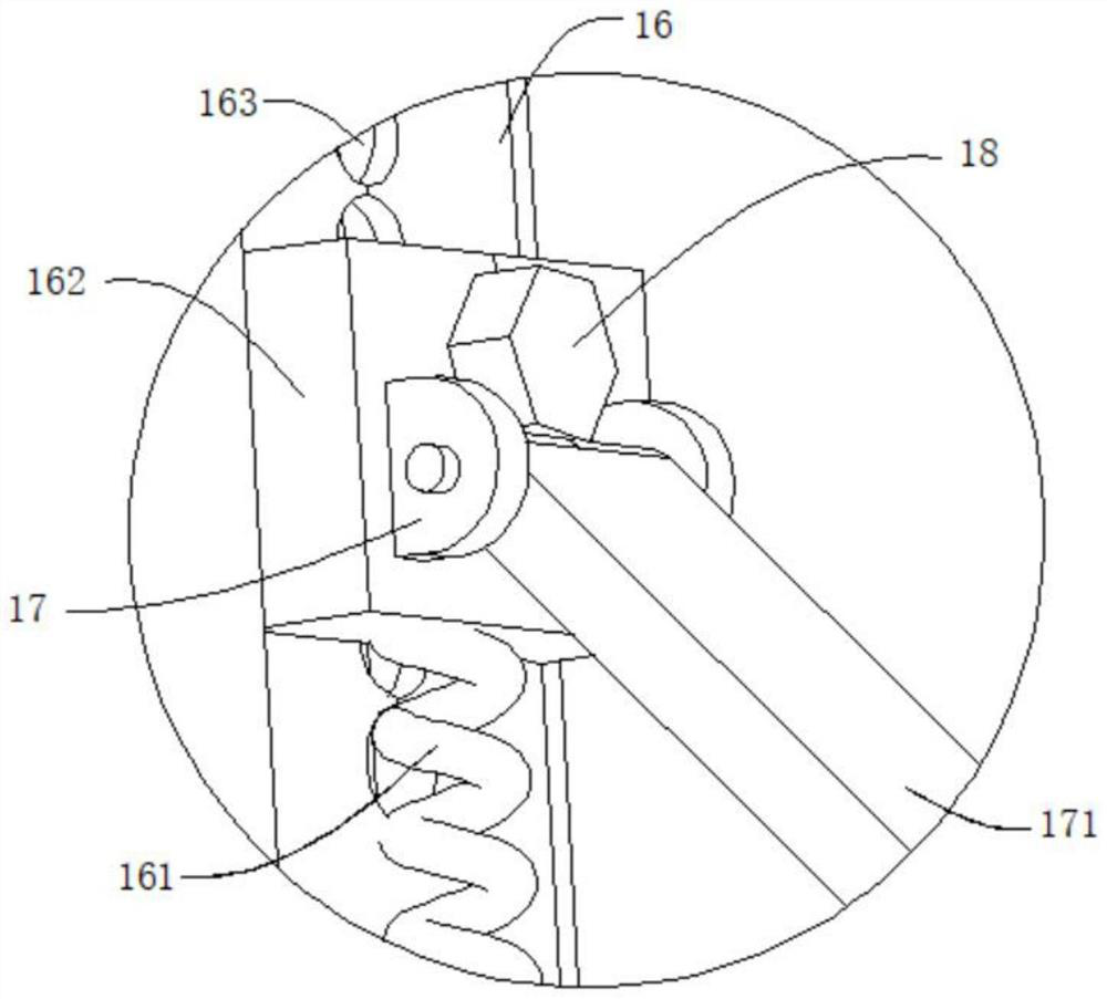
[0048] The outer wall of the movable rod 7 is dug with a groove 16, the inner wall of the groove 16 is connected with an elastic element 161, and the end of the elastic element 161 away from the inner wall of the groove 16 is connected with a moving block 162, and the moving block 162 is slidably connected in the groove 16, and the moving block 162 A matching U-shaped plate 17 is connected to the outer wall of the backing plate 15 , and a connecting rod 171 is movably connected between the two U-shaped plates 17 .
[0049] A first threaded hole 163 is drilled in the inner wall of the groove 16 , and a bolt 18 is threaded in the inner wall of the first threaded h...
PUM
 Abstract
Description
Claims
Application Information