
Automatic film removing method
An automatic, top film technology, used in packaging, cutting and unsealing, conveyor objects, etc., can solve problems such as tipping or bumping, sticking materials, etc.
- Summary
- Abstract
- Description
- Claims
- Application Information
AI Technical Summary
Problems solved by technology
Method used
Image

Examples
Embodiment 1
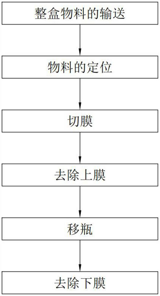
[0073] Such as image 3 Shown, a kind of automatic membrane removal method comprises the following steps:
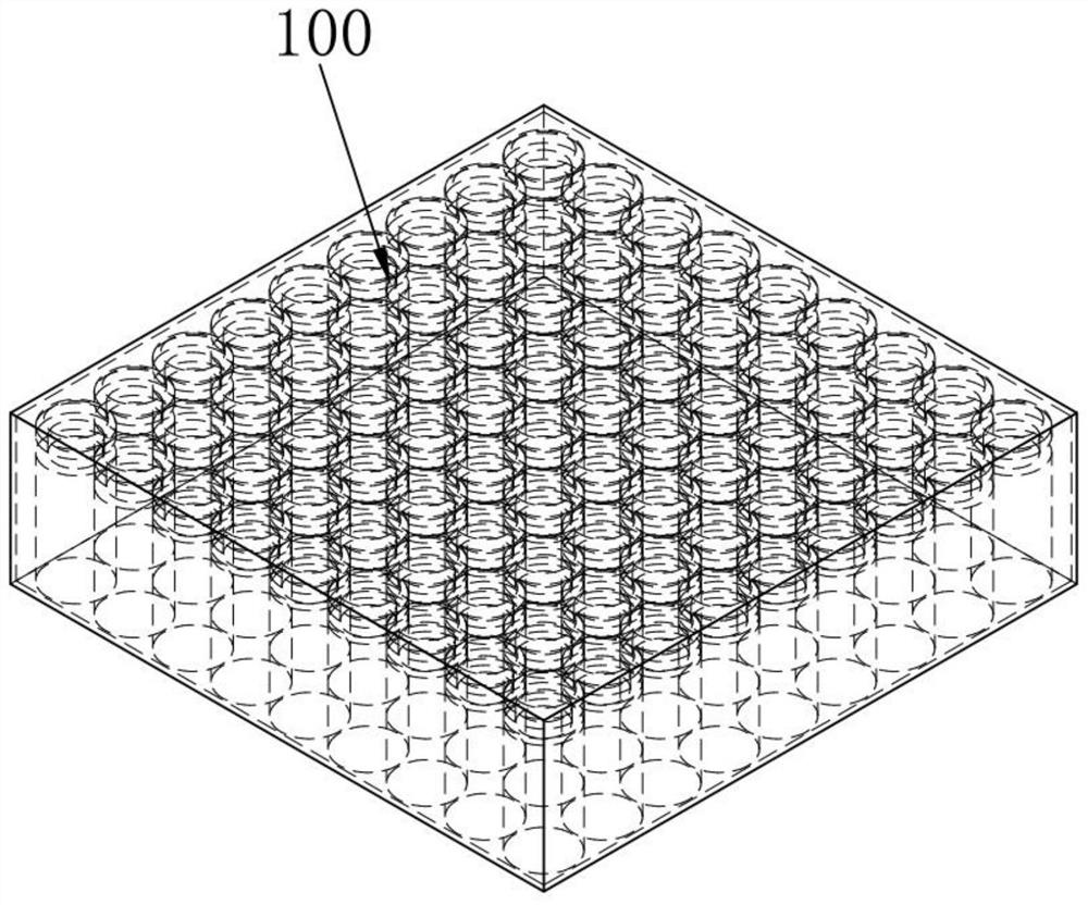
[0074] Step 1. Conveying the whole box of materials, such as Figure 18 As shown, the whole box of materials 100 is transported to the bottom of the film cutting unit 3 by using a belt conveyor, and the guiding effect of the guide plate 13 is used during the transmission process to make the whole box of materials 100 sequentially transported in the same direction;
[0075] Step 2. Positioning of the material. The bottle-taking fork 2321 of the right positioning part 232 and the membrane module 2322 are removed to form an L-shaped right positioning frame, and the L-shaped front end of the left positioning part 222 pushes the whole box of materials 100 to the L-shaped right positioning frame Fitting to complete the positioning of the material; at this time, the vacuum machine 5 is turned on, so that the adsorption hole 212 on the positioning frame 21 absorbs the bottom en...
Embodiment 2
[0090] Such as Figure 4 Shown, an automatic film remover, comprising:
[0091] Feeding unit 1, said feeding unit 1 is responsible for conveying the whole box of material 100 containing the bottle to the bottom of the film cutting unit 3;
[0092] positioning unit 2, such as Figure 5-11 As shown, the positioning unit 2 is arranged at the tail end of the feeding unit 1, and it includes a positioning frame 21, a left positioning assembly 22 and a right positioning assembly 23 respectively arranged on the left and right sides of the positioning frame 21; the left positioning assembly 22 includes a left positioning slide 221 that is slidably arranged on one side of the positioning frame 21, and a left positioning piece 222 that is slidably provided on the top of the left positioning slide 221; The right positioning slide plate 231, slide the right positioning part 232 that is located on the right positioning slide plate 231 top;
[0093] Cutting film unit 3, such as Figure 1...
PUM
 Abstract
Description
Claims
Application Information