Ventilation valve and clothes treatment device

The technology of a clothing treatment device and a ventilation valve can be used in washing devices, other washing machines, household dryers, etc., and can solve problems such as retained dirt.

Pending Publication Date: 2021-09-07
QINGDAO HAIER WASHING MASCH CO LTD +2
View PDF0 Cites 0 Cited by
  • Summary
  • Abstract
  • Description
  • Claims
  • Application Information

AI Technical Summary

Problems solved by technology

[0006] However, no matter the current washing machine is a pulsator type or a drum type, there is generally a large amount of dirt between the inner and outer cylinders of the washing machine. In order to avoid pollutio...

Method used


Image

  • Ventilation valve and clothes treatment device
  • Ventilation valve and clothes treatment device
  • Ventilation valve and clothes treatment device

Examples


Embodiment 1

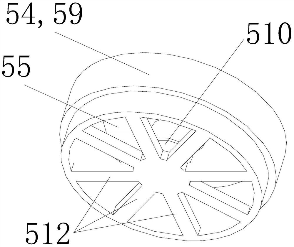
[0063] Such as Figure 3 to Figure 6 As shown, a breathable valve is introduced in this embodiment, which includes a bracket, and a valve piece 55 is installed on the bracket 54; the valve piece 55 has a plurality of slits 56 extending radially to the outer periphery, and the slits 56 connect the valve piece 55 is divided into a plurality of elastic portions 58; the elastic portion 58 is fixedly connected to the bracket 54 on one side of the center of the valve plate, and the elastic portion 58 is suspended on one side of the outer periphery of the valve plate. The floating side of the elastic portion 58 can produce elastic bending deformation to the side of the valve plate 55 .

[0064] By setting slits on the valve plate, the valve plate is composed of multiple independent elastic parts spliced ​​with each other, so that each elastic part of the valve plate can produce bending deformation of the suspended side under the action of pressure difference, and then achieve the pre...

Embodiment 2

[0074] The difference between this embodiment and the first embodiment above is:

[0075] Such as Figure 7 As shown, a two-way venting valve is introduced in this embodiment, which includes a bracket, and a valve plate 55 is installed on the bracket 54; the valve plate 55 has a plurality of slits 56 extending radially to the outer periphery, and the slits 56 connect the valve The sheet 55 is divided into a plurality of elastic parts 58; the elastic part 58 is fixedly connected to the bracket 54 on the side of the center of the valve sheet 55, and the elastic part 58 is suspended on the outer peripheral side of the valve sheet 55. Under the action of the pressure difference on both sides of the valve sheet 55 The suspending side of each elastic portion 58 can produce elastic bending deformation to any direction on both sides of the valve plate 55 .

[0076] In this embodiment, two ends of the sleeve-shaped main body 59 are respectively provided with radially extending connect...

Embodiment 3

[0079] Such as image 3 , Figure 4 , Figure 8 and Figure 9 As shown, a breathable valve is introduced in this embodiment, which includes a bracket 54, a channel is provided on the bracket 54, a valve piece 55 is installed in the channel, the valve piece 55 is connected with the bracket 54 through an elastic member 57, and the valve piece 55 is in the Under the action of the pressure difference on both sides, it can overcome the elastic force of the elastic member 57 to produce displacement and / or overcome the elasticity of its own material to produce elastic deformation.

[0080] By connecting the valve plate to the bracket through the elastic member, the elasticity connected to the valve plate can be moved and / or bent and deformed under the pressure difference, so as to achieve the controllable opening and closing of the vent port under the pressure difference. effect; also, through the above-mentioned settings, the valve plate can be fixedly assembled on the air hole o...


PUM


Abstract

The invention discloses a ventilation valve. The ventilation valve comprises a support, and a channel is formed in the support; a valve plate is installed in the channel; and the valve plate is connected with the support through elastic pieces, and the valve plate can overcome the elastic force of the elastic pieces to generate displacement and/or overcome the elasticity of the material of the valve plate to generate elastic deformation under the action of the differential pressure of the two sides. The invention further discloses a clothes treatment device. The clothes treatment device comprises a drum installed in a shell and forming a sealed water container when a washing machine is in a washing state; and the drum is provided with at least one air hole, and each air hole is provided with the ventilation valve.

Description

technical field [0001] The present invention relates to a clothes treatment device in a household appliance, in particular to a clothes treatment device with a non-porous drum and a drying function, in particular to a non-porous drum with no dehydration holes. A drum-type washing and drying machine, in particular, relates to a ventilation valve applied to the air inlet and outlet of the drum of the above-mentioned clothes processing device. Background technique [0002] With the improvement of people's living standards, washing and drying all-in-one machines, clothes dryers and other equipment with the function of drying clothes have gradually entered the homes of the masses. However, in existing washing and drying machines, clothes dryers and other equipment, the outer cylinder is generally connected with an air duct, and a fan is installed in the air duct to extract the hot and humid air from the outer cylinder, thereby reducing the humidity in the cylinder to dry the clot...

Claims


Application Information

Patent Timeline
IPC IPC(8): D06F37/02D06F58/04
CPCD06F37/02D06F58/04
Inventor 李以民刘海涛金学峰许升赵志强
Owner QINGDAO HAIER WASHING MASCH CO LTD
Why Eureka
Try Eureka