a micro-orifice plate

A technology of micropores and micropores, applied in the field of biochemical detection, can solve the problems of cost, dependence, and large volume, and achieve the effect of automatic biochemical analysis

Active Publication Date: 2020-11-17
SUZHOU UNIV
View PDF6 Cites 0 Cited by
  • Summary
  • Abstract
  • Description
  • Claims
  • Application Information

AI Technical Summary

Problems solved by technology

The 96-plate currently has two main disadvantages: (1) The volume of each well is relatively large, so the sample consumption is relatively large; (2) The liquid exchange operation of the well needs to rely on manual or large-scale automatic operation equipment, which is inconvenient and expensive

Method used


Image

  • a micro-orifice plate
  • a micro-orifice plate
  • a micro-orifice plate

Examples


Embodiment 1

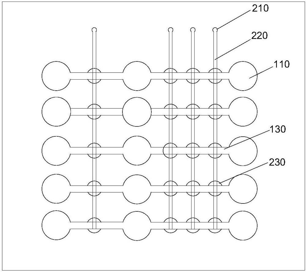
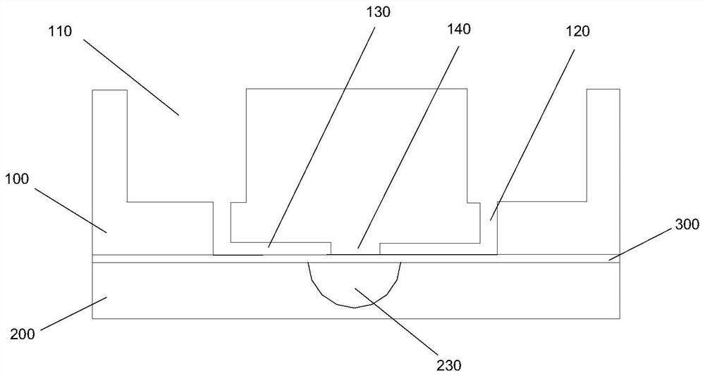
[0037] This embodiment provides a micro-orifice plate, including an upper substrate 100 , a lower substrate 200 and an intermediate film 300 .

[0038] refer to figure 1 , as shown in 3-4, the upper substrate 100 is provided with a plurality of microholes 110 arranged in a matrix of 5×3, each microhole 110 is provided with a communicating hole 120 at the bottom of the hole, and the two transversely adjacent communicating holes 120 They are connected by a flow channel, and at least one break point 140 is set in the flow channel. In this embodiment, 1 and 3 breakpoints 140 are respectively provided in the two transverse channels. The break point 140 functions to block the flow of liquid.

[0039] The lower substrate 200 is provided with cavities 230 corresponding to the breakpoints 140 one by one, so that the cavities 230 form a 5×4 matrix arrangement. Among the four rows of cavities 230 arranged vertically, each row of cavities 230 is provided with a gas interface 210 , and ...

Embodiment 2

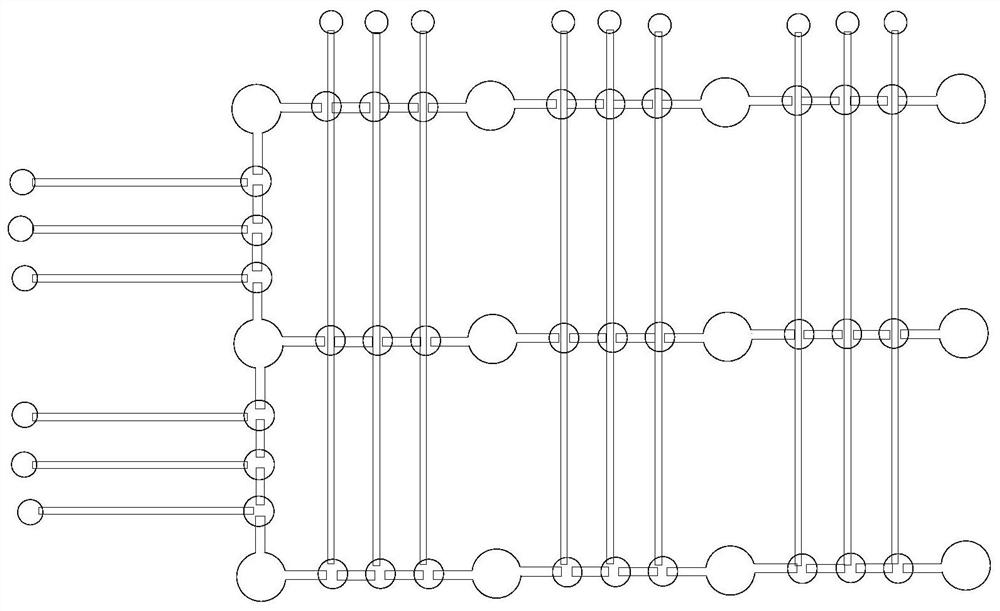
[0042] figure 2 Shows a schematic structural view of a microwell plate according to another embodiment of the present invention. In this embodiment, the upper substrate 100 is provided with a plurality of microwells 110 arranged in a 3×4 matrix, and the bottom of each microwell 110 Each of them is provided with a communication hole 120 , two horizontally adjacent communication holes 120 are connected by a flow channel, and the leftmost column of vertically adjacent two communication holes 120 is connected by a flow channel. There are three breakpoints in each runner.

[0043] The lower substrate 200 is provided with cavities 230 corresponding to the breakpoints 140 one-to-one. Among the nine columns of cavities 230 arranged vertically, each column of cavities 230 is provided with a gas interface 210, and the gas interface 210 is connected to the gas channel 220 through the gas channel 220. The outermost cavity 230 communicates with each other. In the leftmost row of cavitie...


PUM


Abstract

The invention discloses a micro orifice plate, which comprises an upper substrate, a lower substrate and an intermediate film; a micro orifice is characterized in that it comprises an upper substrate, a lower substrate and an intermediate film; the upper substrate is provided with a plurality of micro Holes, at least some of the micropores are connected by flow channels, and at least one breakpoint is provided in the flow channel; cavities corresponding to the breakpoints are provided on the lower substrate, and at least some of the cavities are communicated through gas channels The lower substrate is also provided with a gas interface, and at least part of the cavity communicates with the gas interface through a gas channel; the middle layer film is sandwiched between the upper substrate and the lower substrate, and the upper substrate and the middle layer film are surrounded A plurality of disconnected liquid channels are formed, and a connected gas channel is formed between the lower substrate and the middle film. The micro-orifice plate of the present invention can realize programmed and automatic flow of liquid between wells, thereby realizing automatic biochemical analysis.

Description

technical field [0001] The invention relates to the technical field of biochemical detection, in particular to a micro-orifice plate. Background technique [0002] The 96-well plate is today a common platform in biomedical laboratories, mainly for biochemical assays, such as immunoassays. The 96 plate currently has two main disadvantages: (1) The volume of each well is relatively large, so the sample consumption is relatively large; (2) The liquid exchange operation of the well needs to rely on manual or large-scale automatic operation equipment, which is inconvenient and expensive . [0003] In response to these two shortcomings, we tried to reduce the size of the wells of the 96-well plate, and at the same time, pre-installed all the test solutions needed for biochemical analysis in the wells of the 96-well plate, and then the wells communicated with each other. The flow of liquid between the wells enables automated immunoassays. Contents of the invention [0004] The...

Claims


Application Information

Patent Timeline
Patent Type & Authority Patents(China)
IPC IPC(8): G01N33/53
CPCG01N33/53
Inventor 张秀莉邓权峰罗勇
Owner SUZHOU UNIV
Why Eureka
Try Eureka