Ventilation valve and clothes treatment device
The technology of a clothing treatment device and a ventilation valve can be used in washing devices, other washing machines, household dryers, etc., and can solve problems such as retained dirt.
- Summary
- Abstract
- Description
- Claims
- Application Information
AI Technical Summary
Problems solved by technology
Method used
Image
Examples
Embodiment 1
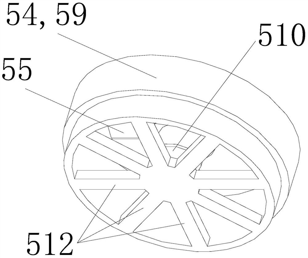
[0058] Such as Figure 3 to Figure 6 As shown, a breathable valve is introduced in this embodiment, which includes a bracket, and a valve piece 55 is installed on the bracket 54; the valve piece 55 has a plurality of slits 56 extending radially to the outer periphery, and the slits 56 connect the valve piece 55 is divided into a plurality of elastic portions 58; the elastic portion 58 is fixedly connected to the bracket 54 on one side of the center of the valve plate, and the elastic portion 58 is suspended on one side of the outer periphery of the valve plate. The floating side of the elastic portion 58 can produce elastic bending deformation to the side of the valve plate 55 .
[0059] By setting slits on the valve plate, the valve plate is composed of multiple independent elastic parts spliced with each other, so that each elastic part of the valve plate can produce bending deformation of the suspended side under the action of pressure difference, and then achieve the pre...
Embodiment 2
[0069] The difference between this embodiment and the first embodiment above is:
[0070] Such as Figure 7As shown, a two-way venting valve is introduced in this embodiment, which includes a bracket, and a valve plate 55 is installed on the bracket 54; the valve plate 55 has a plurality of slits 56 extending radially to the outer periphery, and the slits 56 connect the valve The sheet 55 is divided into a plurality of elastic parts 58; the elastic part 58 is fixedly connected to the bracket 54 on the side of the center of the valve sheet 55, and the elastic part 58 is suspended on the outer peripheral side of the valve sheet 55. Under the action of the pressure difference on both sides of the valve sheet 55 The suspending side of each elastic portion 58 can produce elastic bending deformation to any direction on both sides of the valve plate 55 .
[0071] In this embodiment, two ends of the sleeve-shaped main body 59 are respectively provided with radially extending connecti...
Embodiment 3
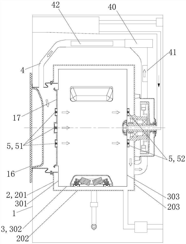
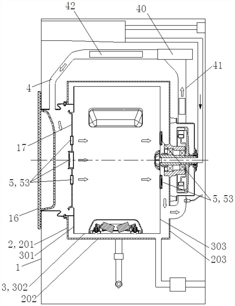
[0074] Such as image 3 , Figure 4 , Figure 8 with Figure 9 As shown, a breathable valve is introduced in this embodiment, which includes a bracket 54, a channel is provided on the bracket 54, a valve piece 55 is installed in the channel, the valve piece 55 is connected with the bracket 54 through an elastic member 57, and the valve piece 55 is in the Under the action of the pressure difference on both sides, it can overcome the elastic force of the elastic member 57 to produce displacement and / or overcome the elasticity of its own material to produce elastic deformation.
[0075] By connecting the valve plate to the bracket through the elastic member, the elasticity connected to the valve plate can be moved and / or bent and deformed under the pressure difference, so as to achieve the controllable opening and closing of the vent port under the pressure difference. effect; also, through the above-mentioned settings, the valve plate can be fixedly assembled on the air hole ...
PUM
 Abstract
Description
Claims
Application Information
 - R&D
- Intellectual Property
- Life Sciences
- Materials
- Tech Scout
- Unparalleled Data Quality
- Higher Quality Content
- 60% Fewer Hallucinations
Browse by: Latest US Patents, China's latest patents, Technical Efficacy Thesaurus, Application Domain, Technology Topic, Popular Technical Reports.
© 2025 PatSnap. All rights reserved.Legal|Privacy policy|Modern Slavery Act Transparency Statement|Sitemap|About US| Contact US: help@patsnap.com


