Clamping mechanism of camshaft grinding machine

A technology of clamping mechanism and camshaft, which is applied to the parts of grinding machine tools, abrasive belt grinders, grinding workpiece supports, etc., which can solve the problem that the camshaft is easy to move, affects the machining accuracy of the camshaft, and cannot clamp the camshaft Force adjustment and safety protection and other issues, to achieve effective clamping and smooth rotation, realize flexible processing, and improve the effect of processing accuracy

Pending Publication Date: 2021-11-26
ZHEJIANG BOXING IND & TRADE
View PDF0 Cites 2 Cited by
  • Summary
  • Abstract
  • Description
  • Claims
  • Application Information

AI Technical Summary

Problems solved by technology

[0004] The clamping mechanism of a camshaft grinder generally includes a headstock and a tailstock, which clamp the camshaft in the middle. The headstock generally needs to drive the camshaft to rotate, and the tailstock can adjust the clamping force on the camshaft. The stability of the clamping of the camshaft by the headstock of the camshaft grinding machine is not good, and the camshaft is easy to move in series during grinding, which affects the machining accuracy of the camshaft; and the current tailstock of the grinding machine cannot self-perceive the clamping of the camshaft. The holding force and the accurate clamping position of the camshaft cannot be stably adjusted and safely protected during the grinding process of the camshaft, so that the flexible processing of the camshaft cannot be achieved

Method used


Image

  • Clamping mechanism of camshaft grinding machine
  • Clamping mechanism of camshaft grinding machine
  • Clamping mechanism of camshaft grinding machine

Examples


Embodiment Construction

[0026] The present invention will be described in detail below in conjunction with accompanying drawing:

[0027] Such as Figure 1-5 Shown:

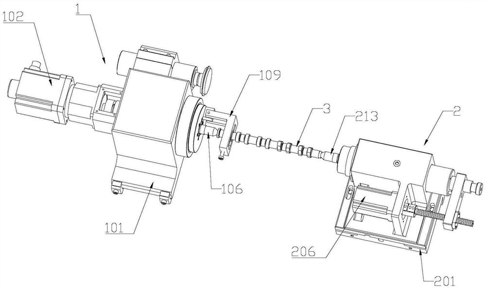
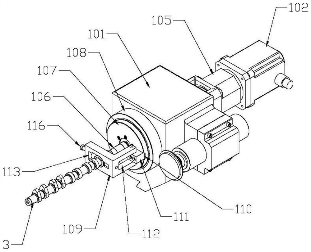
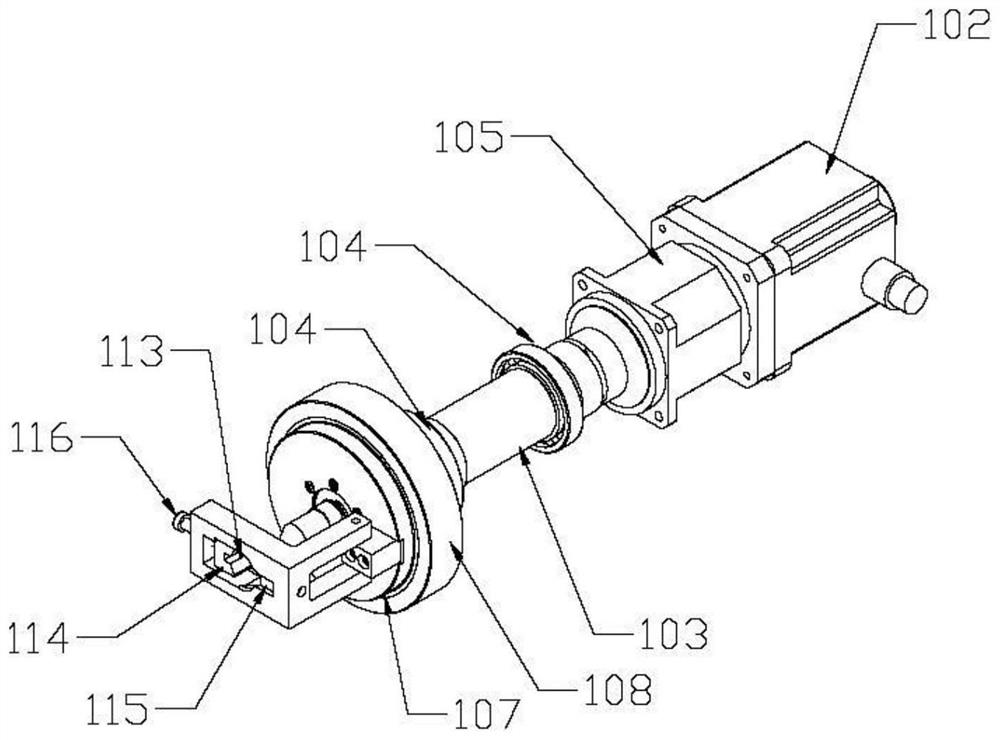
[0028] A clamping mechanism for a camshaft 3 grinding machine, comprising a headstock 1 and a tailstock 2, wherein the headstock 1 includes a headstock seat 101 and a first servo motor 102, the headstock seat 101 is provided with a transverse headstock hole, and the headstock The headstock main shaft 103 is rotatably connected in the frame hole, and both ends of the headstock main shaft 103 are interference-fitted with rolling bearings 104. Fixed connection, one end of the headstock main shaft 103 passes through the headstock hole and is connected with a reducer 105 through a flat key, the reducer 105 is fixedly connected with the output shaft of the first servo motor 102 through a flat key, and the other end of the headstock main shaft 103 passes through the The head frame hole is fixedly connected to the head frame top 106 through a...


PUM


Abstract

The invention relates to the technical field of camshaft machining equipment, and discloses a clamping mechanism of a camshaft grinding machine. The clamping mechanism comprises a headstock and a tailstock, wherein a transverse headstock hole is formed in a headstock seat, a headstock main shaft is connected to the interior of the headstock hole, one end of the headstock main shaft is connected with a first servo, the headstock main shaft is connected with a headstock flange plate, a fixing ring is arranged on the headstock flange plate in a sleeving mode, and the fixing ring is connected to the headstock seat; the headstock flange plate is fixedly connected with a clamp; and the tailstock comprises a tailstock seat, a vertical plate and a tailstock sleeve are fixedly connected to the tailstock seat, a first through hole is formed in the vertical plate, a second through hole is formed in the tailstock sleeve, a second servo motor is connected to the first through hole of the vertical plate, an output shaft of the second servo motor penetrates through the first through hole to be fixedly connected with a lead screw, and the lead screw is in threaded connection with a connecting plate. According to the clamping mechanism, a camshaft can be stably clamped, so that movement is avoided; and the tailstock can also sense the magnitude of the clamping force and whether a workpiece is accurately in place or not, and the clamping force is automatically adjusted in the grinding process, so that the machining safety is guaranteed.

Description

technical field [0001] The invention relates to the technical field of camshaft processing equipment, in particular to a clamping mechanism of a camshaft grinder. Background technique [0002] Camshafts are widely used in gasoline engines or diesel engines to control the opening and closing of cylinder intake and exhaust valves. The quality of its processing directly determines the performance of the engine. [0003] Camshafts are generally made by mold casting, and the surface of cast camshafts is generally rough, but the camshaft runs at high speed in the engine, so the roughness requirements are very high. At present, the grinding and finishing of camshafts are usually done by CNC camshaft grinder Grinding. During grinding, the camshaft is placed in the clamping mechanism of the grinding machine, and the clamping mechanism drives the workpiece to rotate. Through the linkage between the feed movement of the grinding mechanism and the rotational movement of the workpiece, t...

Claims


Application Information

Patent Timeline
Patent Type & Authority Applications(China)
IPC IPC(8): B24B19/12B24B41/06B24B47/22B24B49/00
Inventor 徐刚强周康康胡火明曹毅阚李近蒋文龙李孝禄葛金亮王勇何飞叶李斌王而聪赵家贵张卸伟游平飞
Owner ZHEJIANG BOXING IND & TRADE
Why Eureka
Try Eureka