Charging circuit and electronic equipment

A charging circuit and charger technology, applied in battery circuit devices, circuit devices, current collectors, etc., can solve the problem of low overall charging efficiency, and achieve the effects of reducing voltage ripple, improving stability, and improving overall charging efficiency

Pending Publication Date: 2021-11-26
VIVO MOBILE COMM CO LTD
View PDF0 Cites 0 Cited by
  • Summary
  • Abstract
  • Description
  • Claims
  • Application Information

AI Technical Summary

Problems solved by technology

[0006] The embodiment of the present application provides a charging circuit to solve the problem of low overall charging efficiency of the charging circuit in the prior art

Method used


Image

  • Charging circuit and electronic equipment
  • Charging circuit and electronic equipment
  • Charging circuit and electronic equipment

Examples


Embodiment Construction

[0021] The following will clearly and completely describe the technical solutions in the embodiments of the present application with reference to the drawings in the embodiments of the present application. Obviously, the described embodiments are part of the embodiments of the present application, not all of them. Based on the embodiments in this application, all other embodiments obtained by persons of ordinary skill in the art without creative efforts fall within the protection scope of this application.

[0022] This embodiment provides a charging circuit.

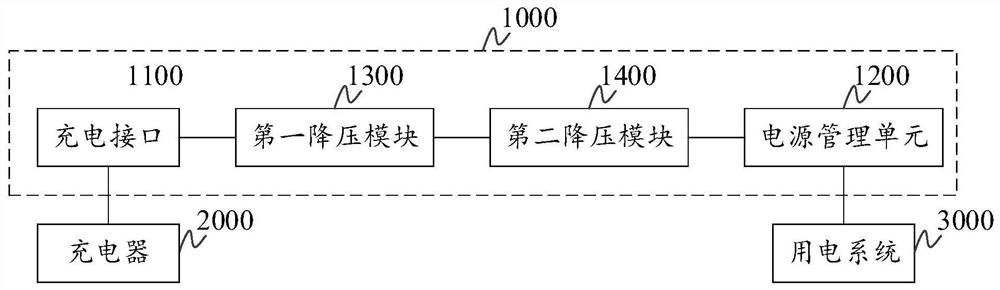
[0023] figure 1 It is a schematic structural diagram of a charging circuit according to an embodiment of the present application.

[0024] Such as figure 1 As shown, the charging circuit 1000 may include a charging interface 1100 , a power management unit 1200 , a first step-down module 1300 and a second step-down module 1400 .

[0025] The charging interface 1100 is used for connecting with the charger 2000 and rece...


PUM


Abstract

The embodiment of the invention provides a charging circuit and electronic equipment. The charging circuit comprises a charging interface, a power management unit, a first voltage reduction module and a second voltage reduction module; the charging interface is used for connecting a charger and receiving a charging signal input by the charger; under the condition that the type of the charger is a first type, the charging signal is subjected to voltage reduction processing through the first path to obtain a first voltage signal, and the power management unit supplies power to a power utilization system according to the first voltage signal; under the condition that the type of the charger is a second type, the charging signal is subjected to voltage reduction processing through a second path to obtain a second voltage signal, and the power management unit supplies power to the power utilization system according to the second voltage signal so as to improve the total charging efficiency of the charging circuit; the first path comprises the second voltage reduction module; the second path includes the first voltage reduction module and a second voltage reduction module.

Description

technical field [0001] The present application relates to the technical field of circuit design, and more specifically, to a charging circuit and an electronic device. Background technique [0002] With the continuous improvement of the performance of smart terminal equipment, the power consumption of the system is increasing, and users have higher and higher requirements for the charging speed and battery life of terminal equipment. The development of fast charging technology is changing with each passing day. At present, the mainstream solution of high-voltage fast charging technology is the solution of dual-cell series charging. [0003] When using a high-voltage fast-charging charger to charge the terminal device, it is necessary to step down the charging signal input by the charger through the first voltage conversion chip, and then perform the step-down process again through the second voltage conversion chip. In order to adjust the voltage of the charging signal to t...

Claims


Application Information

Patent Timeline
Patent Type & Authority Applications(China)
IPC IPC(8): H02J7/00
CPCH02J7/007182Y02B40/00
Inventor 冯宏智
Owner VIVO MOBILE COMM CO LTD
Why Eureka
Try Eureka