Projection light field three-dimensional display device

A stereoscopic display device and projection light technology, applied in the direction of instruments, etc., can solve the problems of low light field density, weakened stereoscopic display effect, etc.

Active Publication Date: 2022-01-11
CHENGDU TECHCAL UNIV
View PDF8 Cites 6 Cited by
  • Summary
  • Abstract
  • Description
  • Claims
  • Application Information

AI Technical Summary

Problems solved by technology

[0004] In order to solve the problem that in the traditional projected light field stereoscopic display device, when the viewer moves away from the screen, the light field density becomes lower and lower, which leads to the gradual weakening of the stereoscopic display effect, the present invention proposes a projected light field stereoscopic display device

Method used


Image

  • Projection light field three-dimensional display device
  • Projection light field three-dimensional display device
  • Projection light field three-dimensional display device

Examples


Embodiment 1

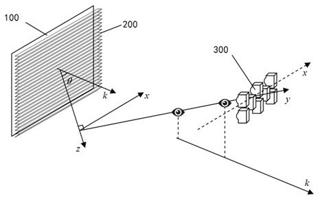
[0020] figure 1 It is a structural principle diagram of a projected light field stereoscopic display device provided in this embodiment. The projected light field stereoscopic display device is composed of a projector array and a one-dimensional retroreflective sheet array 200 . Each projector 300 in the projector array projects a parallax image on the one-dimensional retroreflective sheet array to form an image plane 100 .

[0021] The one-dimensional retroreflective sheet array 200 is composed of a plurality of one-dimensional retroreflective sheets. Such as figure 1 As shown, the one-dimensional retroreflective sheet can be used as a light splitting element in x direction to form a one-dimensional retroreflection. that is x The projector 300 at different positions on the direction, the light emitted by it can be retroreflected by the one-dimensional retroreflective sheet x In the direction, they converge again at their respective positions.

[0022] Please refer to ...

Embodiment 2

[0032] figure 1 It is a structural principle diagram of a projected light field stereoscopic display device provided in this embodiment. The projected light field stereoscopic display device is composed of a projector array and a one-dimensional retroreflective sheet array 200 . Each projector 300 in the projector array projects a parallax image on the one-dimensional retroreflective sheet array to form an image plane 100 .

[0033] The one-dimensional retroreflective sheet array 200 is composed of a plurality of one-dimensional retroreflective sheets. Such as figure 1 As shown, the one-dimensional retroreflective sheet can be used as a light splitting element in x direction to form a one-dimensional retroreflection. that is x The projector 300 at different positions on the direction, the light emitted by it can be retroreflected by the one-dimensional retroreflective sheet x In the direction, they converge again at their respective positions.

[0034] Please refer to ...


PUM


Abstract

In order to solve the problem that in a traditional projection light field three-dimensional display device, when a viewer moves away from a screen, the light field density is lower and lower, so that the three-dimensional display effect is gradually weakened, the invention provides a projection light field three-dimensional display device. The projection light field three-dimensional display device is composed of a projector array and a one-dimensional retroreflector sheet array. The one-dimensional retroreflection sheet array is composed of a plurality of one-dimensional retroreflection sheets. And the normal directions of the one-dimensional retroreflective sheets are consistent and are not parallel to the normal of the image plane. Projectors in the projector array are densely arranged in any form, and each projector respectively projects a parallax image. Light generated by any projector is converged on a straight line after being retroreflected, and the straight line is not perpendicular to the normal direction of an image plane. When a viewer is far away from the screen along the straight line direction, the light field viewed by the viewer does not change any more, so that different viewers in front and back can see consistent three-dimensional images.

Description

technical field [0001] The invention belongs to the technical field of light field stereoscopic display, and more specifically, the invention relates to a projected light field stereoscopic display device. Background technique [0002] The normal line of the stereoscopic image of the traditional projected light field stereoscopic display device is parallel to the normal line of the light splitting element. When performing stereoscopic display, the light field changes along the normal direction of the stereoscopic image. When the viewer moves away from the screen, the light field changes. The density is getting lower and lower, which leads to the gradual weakening of the stereoscopic display effect. Therefore, the present invention proposes a projection light field stereoscopic display device. In this device, the normal line of the stereoscopic image is no longer parallel to the normal line of the light splitting element, so that when moving away from the screen along a speci...

Claims


Application Information

Patent Timeline
Patent Type & Authority Applications(China)
IPC IPC(8): G02B30/35
CPCG02B30/35
Inventor 吕国皎周咏郑骊
Owner CHENGDU TECHCAL UNIV
Why Eureka
Try Eureka