

Chair like massage machine
A seat-type and chair-back technology, applied in the field of seat-type massage machines, can solve problems such as inability to massage
- Summary
- Abstract
- Description
- Claims
- Application Information
AI Technical Summary
Problems solved by technology
Method used
Image

Examples
Embodiment 1
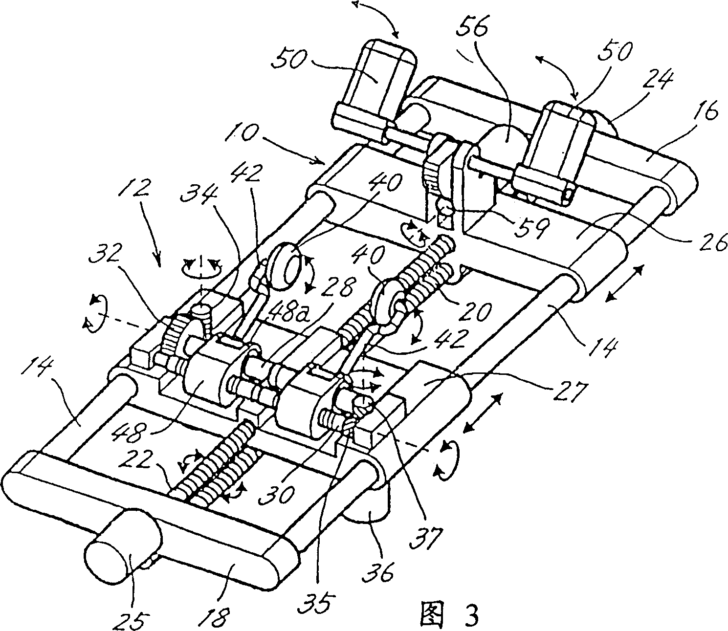
[0034] Describe a kind of massage machine, this massage machine is loaded with 2 massage units 10,12 up and down, each massage unit is connected with the driving source for lifting and lowering independently respectively, and can move up and down, and the upper and lower massage units respectively have a device as a treatment finger driving device. Motor 56, 33, 36.
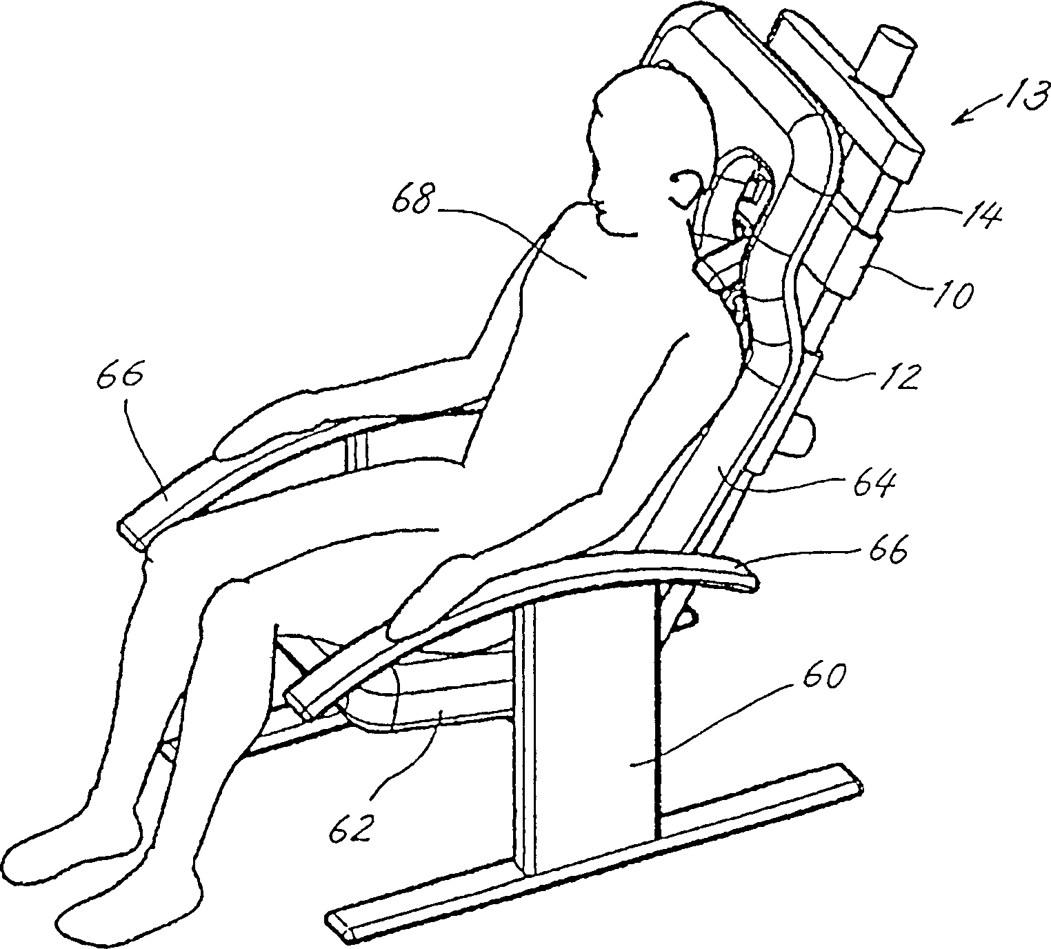
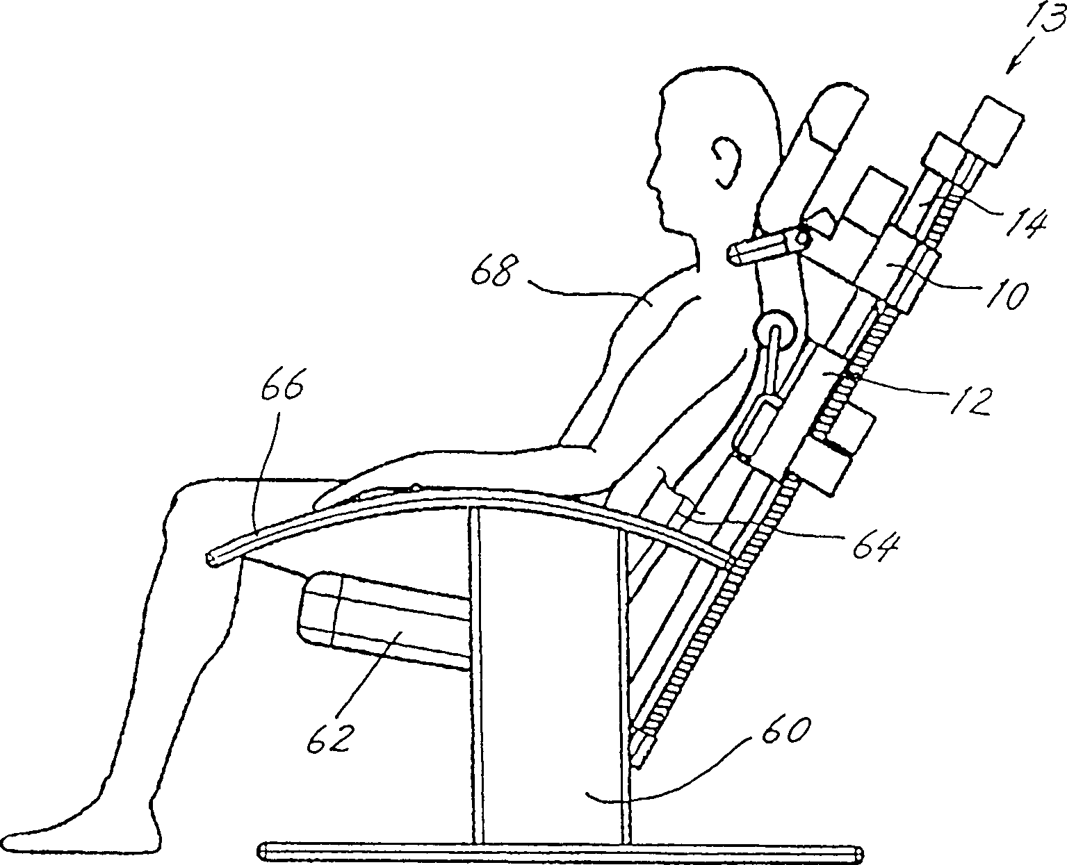
[0035] figure 1 It is a perspective view showing a state where a person to be treated 68 sits on the chair-type massage machine 13 of the present invention. figure 2 is its side view.
[0036] The chair 60 equipped with the massage units 10 and 12 has a seat 62 on which a person to be treated 68 sits, a seat back 64 formed upward from the rear end of the seat, and armrests 66 provided on both sides of the seat.
[0037] The central opening of the chair back 64 protrudes from the opening where the treatment fingers of the massage units 10 and 12 described later protrude. The guide frame 14 is formed along the...
Embodiment 2
[0067] Describe a kind of massage machine, this massage machine is loaded with 2 massage units 10,12 up and down like embodiment 1, and each massage unit is connected with independent lifting drive source 24,25 respectively, can move up and down, there is no treatment on the upper unit 10 The driving source of the finger 50 is to branch and transmit the power of the motor 33 arranged in the lower unit 12 through the power transmission device, and then perform the action of the treatment fingers 50 and 50 of the upper unit 10 .
[0068] In addition, since it is the same as that of the first embodiment except for the branching of the power as the power transmission device and the transmission mechanism, the description of the overlapping parts will be omitted.
[0069] Figure 7 It is the perspective view of the massage mechanism of embodiment 2, Figure 8 To see from the direction of arrow VIII Figure 7 An enlarged view of the main part of the massage unit 10, 12 of .
[00...
Embodiment 3
[0077] In the above-mentioned embodiment, use the control cable 71 to transmit power to the treatment fingers 50, 50 of the upper unit 10 and make it move, and the control cable 71 is connected to the motor 33 of the lower unit 12 and can transmit its power, but in this embodiment In the example to be described, the driving force of the front and rear motor 33 of the lower unit 12 is transmitted to the treatment fingers 50, 50 of the upper unit 10 using a cam mechanism. In addition, since it is the same as that of the first embodiment except for the power transmission mechanism of the upper unit, the description of the overlapping parts will be omitted.
[0078] Figure 9A and Figure 9B show and Figure 8 In the diagram of the same mechanism part, a cam 80 is formed at the end of the front-rear shaft 28 instead of the rod 70 . The cam 80 is provided with a rod 81 slidable in the vertical direction along the peripheral surface of the cam, and the rod 81 protrudes forward from t...
PUM
 Abstract
Description
Claims
Application Information