Alarm control circuit suitable for fault guiding safety of urban rail metro vehicle

A technology for controlling circuit and vehicle faults, which is applied to railway signal and safety, signal indicators on vehicles, railway signals, etc., can solve problems such as vigilance protection function failure, failure to trigger emergency braking, etc., to optimize vigilance control logic, Flexible use and safe effect

Pending Publication Date: 2022-04-29
CRRC DALIAN CO LTD
View PDF6 Cites 0 Cited by
  • Summary
  • Abstract
  • Description
  • Claims
  • Application Information

AI Technical Summary

Problems solved by technology

[0007] A vigilance control circuit suitable for failure-oriented safety of urban rail subway vehicles. The vigilance control circuit can effectively solve the problem of disconnection of a vigilance circuit line or a certain device in the circuit. At this time, the vigilance protection function fails and cannot trigger an emergency Braking problems;

Method used


Image

  • Alarm control circuit suitable for fault guiding safety of urban rail metro vehicle
  • Alarm control circuit suitable for fault guiding safety of urban rail metro vehicle

Examples


Embodiment 1

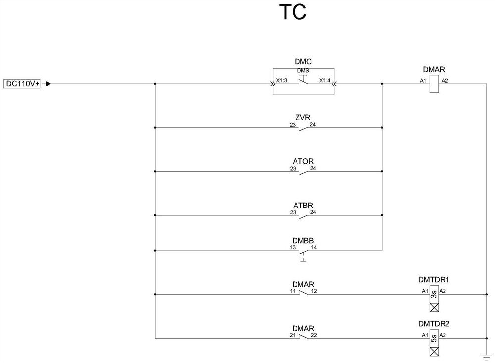
[0031] In order to better illustrate the beneficial effects of the circuit of the present invention, take an existing domestic subway vehicle that has been successfully operated for many years as an example, the vigilance control circuit diagram is as follows figure 1 shown.

[0032] The alert circuit only forms a logic circuit independently when the driver's cab is activated. The specific control logic and operation are:

[0033] (1) After the vehicle is activated by the battery and the operating terminal is activated, in a static state, since the "zero speed" relay ZVR is energized, its normally open contacts are closed, so that the vigilance relay DMAR coil is energized, and its two normally closed contacts Disconnect, so that the electric delay action alert relay DMTDR1 and DMTDR2 can not be powered, and the follow-up control logic is cut off. This state is equivalent to bypassing the driver to trigger the vigilance function by operating the main handle of the controller ...

Embodiment 2

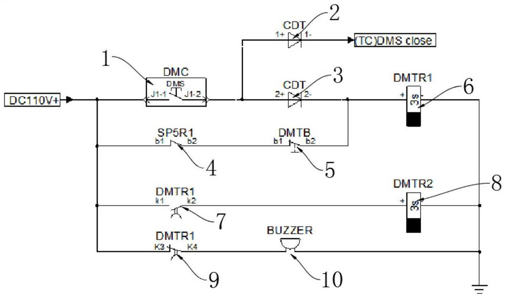
[0038] Please refer to figure 2 As shown, the present invention provides a kind of vigilance control circuit suitable for urban rail subway vehicle fault-oriented safety;

[0039] The vigilance control circuit can effectively solve the problem that the vigilance circuit line or a certain device in the circuit is disconnected due to a fault, and the vigilance protection function fails at this time, and the emergency braking cannot be triggered;

[0040] The vigilance control circuit includes vigilance switch 1 of the main handle of the driver controller, one end of the vigilance switch 1 of the main handle of the driver controller is connected with the second console diode terminal row CDT3, and the other end of the vigilance switch 1 of the main handle of the driver controller is connected with a zero speed Relay 4, the second power-off delay action alert relay contact 7 and the fourth power-off delay action alert relay contact 9, the other end of the zero-speed relay 4 is co...


PUM


Abstract

The invention relates to the technical field of urban rail metro vehicles, in particular to an alert control circuit suitable for fault guiding safety of an urban rail metro vehicle. Comprising a driver controller main handle alert switch, one end of the driver controller main handle alert switch is connected with a second console diode terminal strip, and the other end of the driver controller main handle alert switch is connected with a zero-speed relay, a second power-off delay action alert relay contact and a fourth power-off delay action alert relay contact. The other end of the zero-speed relay is connected with a vigilance test button; one end, far away from the zero-speed relay, of the vigilance test button is connected with the second console diode terminal strip; according to the invention, the existing vigilance control logic is optimized, and the existing shortages are eliminated, so that the vigilance function is greatly and flexibly applied. And the vehicle operation safety is ensured to a great extent while the vehicle operation is met.

Description

technical field [0001] The invention relates to the technical field of urban rail subway vehicles, in particular to a vigilance control circuit suitable for fault-oriented safety of urban rail subway vehicles. Background technique [0002] The vigilance control circuit of urban rail subway vehicles is one of the important components of the vehicle control logic. It belongs to the vehicle control logic and operation skills that urban rail subway drivers must be proficient in. The function of vigilance logic is defined as preventing the driver from leaving the controller handle for some reason (such as falling asleep and leaving the driver's cab when the vehicle is running, etc.) Functional logic, including recording the driver's operation through TCMS, triggering a buzzer reminder and triggering emergency braking after leaving the handle. [0003] At present, the vigilance control circuit of urban rail subway vehicles is relatively simple, and there are few additional pract...

Claims


Application Information

Patent Timeline
Patent Type & Authority Applications(China)
IPC IPC(8): B61L15/00B60T7/12
CPCB61L15/00B61L15/0081B60T7/124
Inventor 李雨张哲韦林吴英帅张晓亮王尔为尹智勇
Owner CRRC DALIAN CO LTD
Why Eureka
Try Eureka