Rotational flow vertical shaft flood discharge tunnel with staggered platform type volute chamber small flip bucket

A technology of flood discharge tunnel and vortex chamber, which is applied in marine engineering, construction, barrage/weir, etc., can solve the problems of increased risk of cavitation and cavitation on the shaft wall, increased engineering construction difficulty, complicated structure of aeration facilities, etc. The ability to resist cavitation and cavitation, reduce the difficulty of construction, and the effect of reducing the difficulty of construction

Pending Publication Date: 2022-05-06
YANGLING VOCATIONAL & TECHN COLLEGE
View PDF1 Cites 0 Cited by
  • Summary
  • Abstract
  • Description
  • Claims
  • Application Information

AI Technical Summary

Problems solved by technology

[0004] In view of the above-mentioned related technologies, the applicant believes that in the practical application of related technologies, the height of the shaft often needs to be increased, and the risk of cavitation and cavitation erosion on the wall of the shaft also increases accordingly. facilities to improve the anti-cavitation cavitation ability of the vortex chamber and shaft wall, and building a separate aeration facility will increase the engineering cost, and the structure of a separate aeration facility is usually more complicated, which will also increase the difficulty of engineering construction

Method used


Image

  • Rotational flow vertical shaft flood discharge tunnel with staggered platform type volute chamber small flip bucket
  • Rotational flow vertical shaft flood discharge tunnel with staggered platform type volute chamber small flip bucket
  • Rotational flow vertical shaft flood discharge tunnel with staggered platform type volute chamber small flip bucket

Examples


Embodiment 1

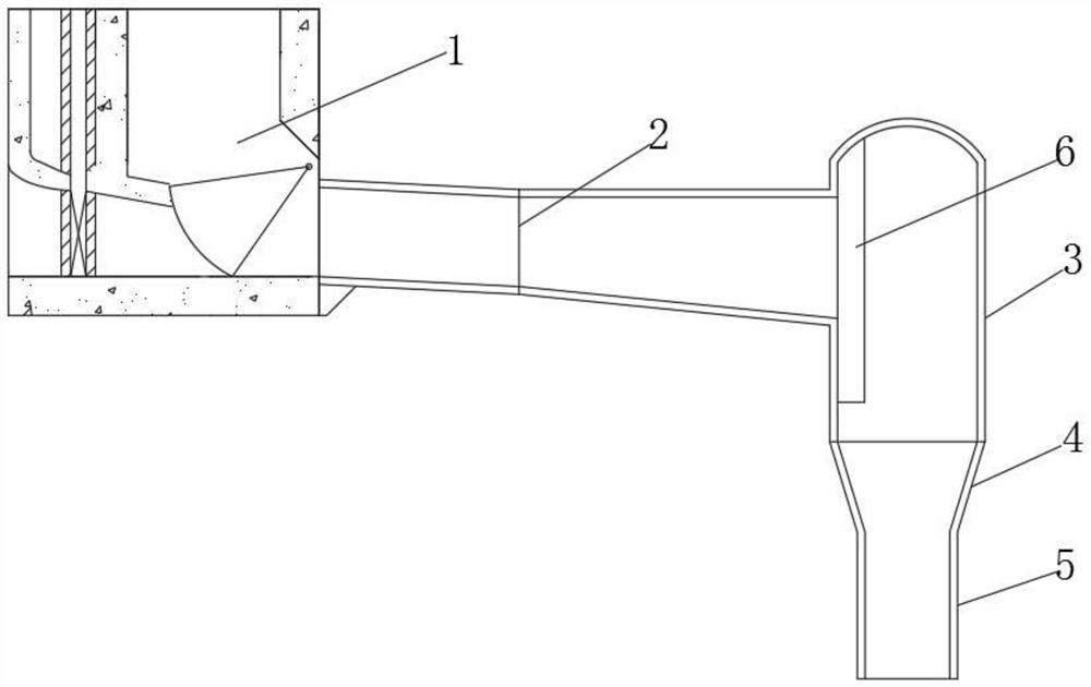
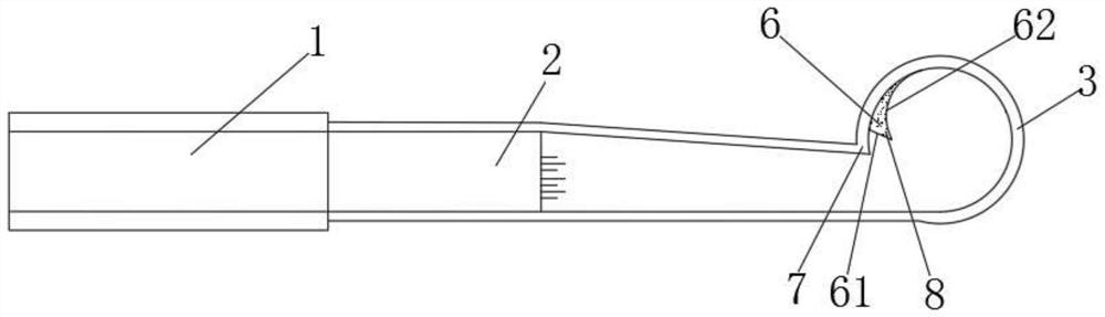
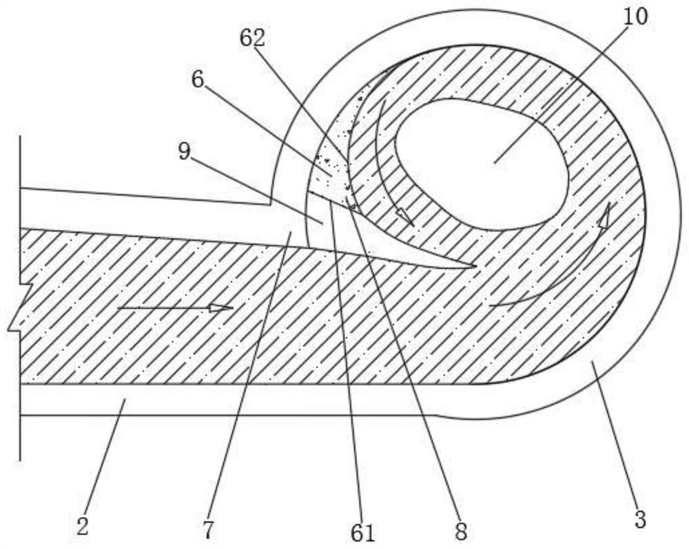
[0023] A swirl shaft flood discharge tunnel with staggered vortex chambers and small ridges, refer to figure 1 , figure 2 , including the sluice chamber inlet 1, the upper flat section 2, the vortex chamber 3, the constriction section 4 and the vertical shaft straight section 5 connected in sequence, and the inner wall of the vortex chamber 3 close to the upper flat section 2 is provided with a diversion ridge 6 , the diversion riser 6 includes a vertical surface 61 and a diversion arc surface 62 intersecting the vertical surface 61, combined with image 3 , the swirl shaft flood discharge tunnel also includes the incoming flow aeration sill 7 and the swirl aeration sill 8; the incoming flow aeration sill 7 flows along the incoming water body from the vertical wall of the upper flat section 2 close to the diversion sill 6 The end of the direction to the vertical surface 61 of the diversion riser 6 suddenly expands to form, and the swirl aeration riser 8 is formed by the div...

Embodiment 2

[0028]The difference between this embodiment and Embodiment 1 is that in this embodiment, when building the diversion riser 6, the overall position of the diversion riser 6 is kept unchanged, and the diversion riser in Embodiment 1 is reduced. 6, the specific implementation method is: the vertical surface 61 of the diversion riser 6 is translated in a direction away from the upper flat section 2, the position of the diversion arc surface 62 of the diversion riser 6 remains unchanged, and the diversion The translation direction of the vertical surface 61 of the raised ridge 6 is perpendicular to the flow direction of the incoming water body in the upper flat section 2, and the vertical surface 61 of the diversion raised ridge 6 is parallel to the vertical wall surface of the upper flat section 2, and at this time the vertical The arc length of the side wall of the vortex chamber 3 between the intersection line of the straight face 61 and the inner wall of the vortex chamber 3 to...


PUM


Abstract

A rotational flow vertical shaft flood discharge tunnel with a staggered table type volute chamber flip bucket comprises a lock chamber inlet, an upper flat section, a volute chamber, a contraction section and a vertical shaft straight section, a flow guide flip bucket is arranged on the inner side wall, close to one side of the tail end of the upper flat section in the water flow direction, of the volute chamber, and the flow guide flip bucket comprises a vertical face and a flow guide arc face intersecting with the vertical face. The rotational flow vertical shaft spillway tunnel further comprises an incoming flow aerator and a rotational flow aerator. The incoming flow aerator is formed by sudden expansion from the tail end, in the water flow direction, of the vertical wall face of the side, close to the flow guide flip bucket, of the upper flat section to the vertical face of the flow guide flip bucket, and the rotational flow aerator is formed by sudden expansion from the tail end, in the water flow direction, of the flow guide arc face of the flow guide flip bucket to the inner side wall of the volute chamber through the vertical face. The method has the effect of improving the cavitation and cavitation erosion resistance of the volute chamber and the inner side wall face of the vertical shaft straight section.

Description

technical field [0001] The invention relates to the field of flood discharge and energy dissipation in water conservancy and hydropower projects, in particular to a swirl shaft flood discharge tunnel with staggered vortex chambers and small ridges. Background technique [0002] The swirl shaft flood discharge tunnel is an energy dissipator that uses the rotation of water flow and incorporates a large amount of gas to increase the turbulent intensity of the water flow and dissipate energy itself. The energy effect is better, and it has attracted more and more attention from the field of water conservancy and hydropower engineering; especially as my country is currently in the stage of blowout development of hydropower construction, many high dams and large reservoirs with high water head, large flow, and deep canyons are under construction or In the planning stage, in the case that conventional discharge structures cannot achieve flood discharge and energy dissipation well, swi...

Claims


Application Information

Patent Timeline
Patent Type & Authority Applications(China)
IPC IPC(8): E02B8/06
CPCE02B8/06
Inventor 夏鹏飞郝红科杨正丽刘文霍倩倩韩红亮杜万军马琳马雪琴宋冰
Owner YANGLING VOCATIONAL & TECHN COLLEGE
Why Eureka
Try Eureka