A kind of swirl shaft flood discharge tunnel with vortex chamber aeration sill
A technology of aerated sills and flood discharge tunnels, which is applied in sea area engineering, construction, barrage/weir, etc., can solve the problems of increased project cost, complex aerated structure, and increased risk of cavitation and cavitation on the shaft wall, and reduce construction costs. Difficulty, increase the gas concentration, improve the effect of anti-cavitation cavitation performance
- Summary
- Abstract
- Description
- Claims
- Application Information
AI Technical Summary
Problems solved by technology
Method used
Image
Examples
Embodiment 1
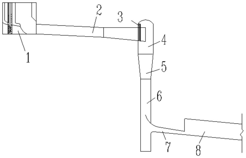
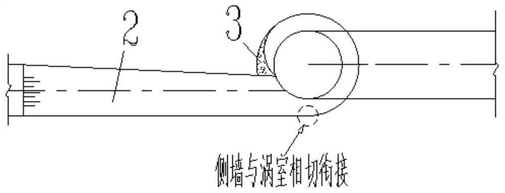
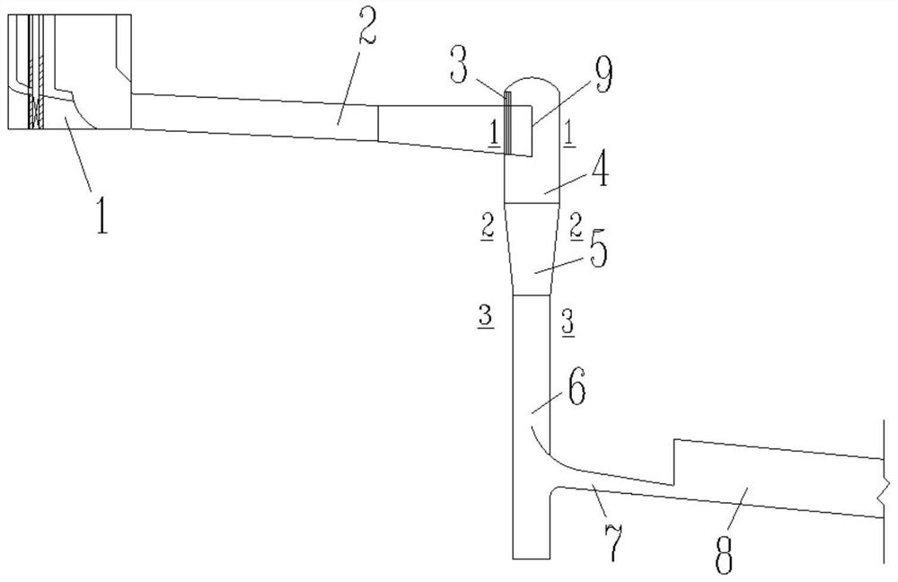
[0026] This embodiment provides a swirl shaft flood discharge tunnel with a vortex chamber aeration sill. The flood discharge tunnel is composed of a sluice chamber inlet 1, an upper flat section 2, a vortex chamber 4, a contraction section 5, a shaft straight section 6, and an outlet pressure slope. Section 7 and the subsequent lower horizontal drainage section 8, the vortex chamber is provided with a small shaft sill 3, the end of the side wall of the upper plane section is located in the vortex chamber, intersects with the wall surface of the vortex chamber, and the end is close to the vortex chamber. The wall surface of the chamber forms a vertical aeration ridge 7 attached to the wall surface of the vortex chamber, so that when the water flows through, an aeration cavity is formed between the aeration ridge and the wall surface of the vortex chamber to realize aeration.
[0027] During construction design, a vertical aeration sill is formed in the vortex chamber by moving ...
Embodiment 2
[0029] This embodiment provides a swirl shaft flood discharge tunnel with a vortex chamber aeration sill. The flood discharge tunnel is composed of a sluice chamber inlet 1, an upper flat section 2, a vortex chamber 4, a contraction section 5, a shaft straight section 6, and an outlet pressure slope. Section 7 and the subsequent lower horizontal drainage section 8, the vortex chamber is provided with a vertical well sill 3, the side wall of the upper plane section intersects with the arc wall of the vortex chamber, and the end of the side wall enters the vortex chamber, forming The vertical aeration sill 7 attached to the wall of the vortex chamber enables an aeration cavity to be formed between the aeration sill and the wall of the vortex chamber when water flows through, thereby realizing aeration.
[0030] During the construction design, a vertical aeration sill is formed in the vortex chamber by shifting the side wall tangentially connected to the vortex chamber to the vort...
PUM
 Abstract
Description
Claims
Application Information
 - R&D
- Intellectual Property
- Life Sciences
- Materials
- Tech Scout
- Unparalleled Data Quality
- Higher Quality Content
- 60% Fewer Hallucinations
Browse by: Latest US Patents, China's latest patents, Technical Efficacy Thesaurus, Application Domain, Technology Topic, Popular Technical Reports.
© 2025 PatSnap. All rights reserved.Legal|Privacy policy|Modern Slavery Act Transparency Statement|Sitemap|About US| Contact US: help@patsnap.com


