Projection light source and projection equipment

A projection and light source technology, applied in optics, instruments, projection devices, etc., can solve the problem of large volume of projection light source, achieve small size, realize miniaturization, and improve the effect of display

Pending Publication Date: 2022-06-28
QINGDAO HISENSE LASER DISPLAY CO LTD
View PDF0 Cites 0 Cited by
  • Summary
  • Abstract
  • Description
  • Claims
  • Application Information

AI Technical Summary

Problems solved by technology

[0006] The application provides a projection light source and projection equipment, which can solve the problem of large projection light source

Method used


Image

  • Projection light source and projection equipment
  • Projection light source and projection equipment
  • Projection light source and projection equipment

Examples


Embodiment Construction

[0028] In order to make the objectives, technical solutions and advantages of the present application clearer, the embodiments of the present application will be further described in detail below with reference to the accompanying drawings.

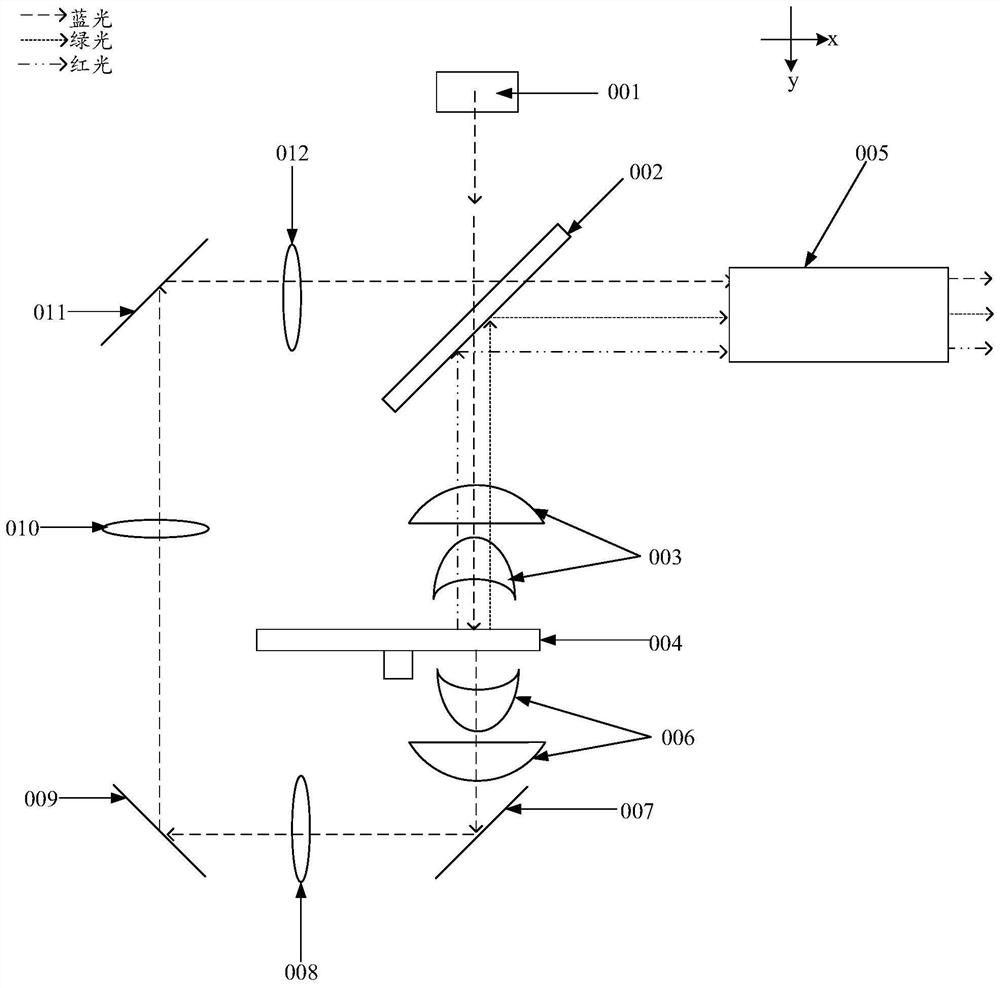
[0029] figure 1 It is a schematic structural diagram of a projection light source provided by the related art. like figure 1 As shown, the projection light source includes: a laser 001 , a dichroic mirror 002 , a first collimating lens group 003 , a fluorescent wheel 004 , a relay circuit system and a light guide 005 . The dichroic mirror 002 , the first collimating lens group 003 and the fluorescent wheel 004 are located on the light-emitting side of the laser 001 , and are sequentially arranged along the light-emitting direction of the laser 001 . The relay loop system includes: a second collimating lens group 006, a first reflecting lens 007, a first collimating lens 008, a second reflecting lens 009, a second collimating lens 010, a...


PUM


Abstract

The invention discloses a projection light source and projection equipment, and belongs to the technical field of photoelectricity. Two laser devices in the projection light source emit laser to two corresponding focus lenses respectively; each focus lens is used for converging incident laser to a transmission area corresponding to the focus lens in the light combination lens, and the transmission area is used for transmitting the incident laser to the convergent lens; the position, irradiated by the laser emitted by the two transmission areas in the light combination lens, of the convergent lens is symmetric about the optical axis of the convergent lens, and the convergent lens is used for converging the incident laser to the fluorescent wheel; different areas in the fluorescent wheel are irradiated by laser in the rotating process of the fluorescent wheel; wherein the first area is used for reflecting laser, and the second area is used for emitting fluorescence under excitation of the laser; fluorescent light emitted by the first area and laser light reflected by the second area penetrate through the convergent lens and are emitted to the reflection area; the reflection area is used for reflecting incident light in the target direction. The problem that the projection light source is large in size is solved. The invention is used for emitting light.

Description

[0001] The embodiments of this application claim the priority of a Chinese patent application with an application number of 202111135121.3 and an invention title of “projection light source and projection device” filed on September 27, 2021, the entire contents of which are incorporated into the embodiments of this application by reference. technical field [0002] The present application relates to the field of optoelectronic technology, and in particular, to a projection light source and projection equipment. Background technique [0003] With the development of optoelectronic technology, the requirements for the miniaturization of projection light sources in projection equipment are getting higher and higher. [0004] In related technologies, such as figure 1 As shown, the projection light source includes: a laser 001, a dichroic mirror 002, a first collimating lens group 003, a fluorescent wheel 004, a light pipe 005 and a relay loop system, the relay loop system includi...

Claims


Application Information

Patent Timeline
Patent Type & Authority Applications(China)
IPC IPC(8): G03B21/20
CPCG03B21/204G03B21/206G03B21/208G03B21/2066
Inventor 王强
Owner QINGDAO HISENSE LASER DISPLAY CO LTD
Why Eureka
Try Eureka