Fluid curvature engine, fluid curvature engine equipment and control method of fluid curvature engine equipment

A curvature and fluid technology, which is applied in fluid curvature engine and fluid curvature engine equipment and its control field, can solve problems such as insufficient lift and small engine thrust-to-weight ratio, and achieve the effect of increased self-control, large power load, convenient and safe operation

Pending Publication Date: 2022-07-08
田贵川
View PDF0 Cites 0 Cited by
  • Summary
  • Abstract
  • Description
  • Claims
  • Application Information

AI Technical Summary

Problems solved by technology

[0004] The object of the present invention is to provide a fluid curvature engine, a fluid curvature engine equipment and its control method, which can fully exert the combined effect of fluid viscosity and high-speed fluid inertia to prevent atmospheric pressure from generating a low pressure area in the lower curvature area of ​​the upper convex surface and generate lift. The principle is to solve the problems of the existing engines with small thrust-to-weight ratio and insufficient lift

Method used


Image

  • Fluid curvature engine, fluid curvature engine equipment and control method of fluid curvature engine equipment
  • Fluid curvature engine, fluid curvature engine equipment and control method of fluid curvature engine equipment
  • Fluid curvature engine, fluid curvature engine equipment and control method of fluid curvature engine equipment

Examples


Embodiment 1

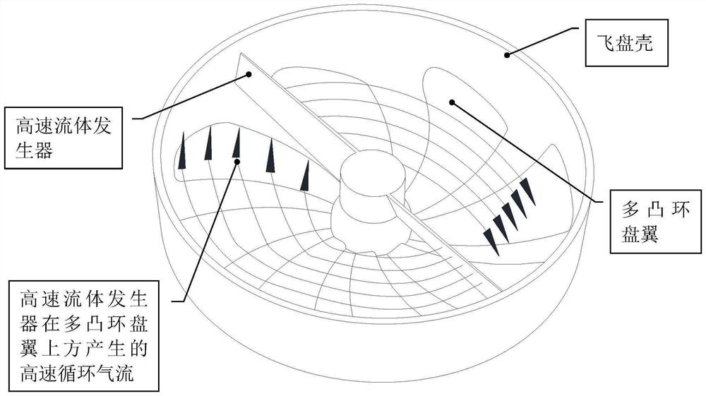
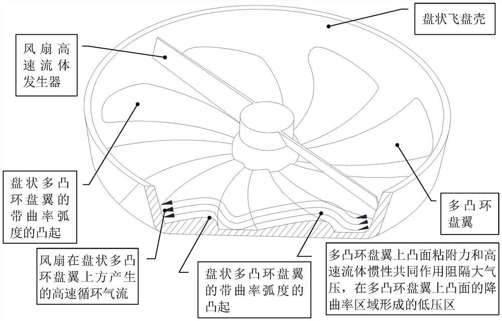
[0063] Example 1 Disc Fan Fluid Curvature Engine Example

[0064] like Figure 1 to Figure 2 As shown, this embodiment provides a fluid curvature engine, specifically a disc-shaped fan fluid curvature engine, which is characterized in that it is mainly composed of a flying disc shell, a multi-convex ring disc wing, and a high-speed fluid generator. The flying disc shell is a disc-shaped open half-cavity, the multi-convex ring disc wing is disc-shaped, and the upper surface of the multi-convex ring disc wing has a plurality of protrusions with curvature radians along the circumferential fluid flow direction, Each convex curved surface with a curvature radian is similar to a single-lobed wing, and the multi-convex disc wing is equivalent to a combination of sequentially connecting multiple sections of wings in a manner of leading edge to trailing edge along the circumferential fluid flow direction. The multi-convex ring disc wing is integrated with the flying disc shell, that i...

Embodiment 2

[0066] Example 2 Polygon annular built-in generator fluid curvature engine example

[0067] like Figure 4 As shown, this embodiment provides a fluid curvature engine, specifically a multi-sided annular built-in generator fluid curvature engine, characterized in that it is mainly composed of a flying disc shell, a multi-convex ring disc wing, and a high-speed fluid generator. The flying disc shell is an annular open half-cavity, the multi-convex ring disc wing is annular, and the upper surface of the multi-convex ring disc wing has a plurality of protrusions with curvature radians along the circumferential fluid flow direction. Each convex curved surface with a curvature radian is similar to a single-lobed wing, and the multi-convex disc wing is equivalent to a combination of connecting multiple sections of wings sequentially in the manner of leading edge and trailing edge along the circumferential fluid flow direction. The multi-convex ring disc wing is integrated with the f...

Embodiment 3

[0069] Example 3 Air-collecting structure fluid curvature engine airborne equipment example

[0070] like Figure 6 to Figure 7 As shown, this embodiment provides a fluid-curvature engine airborne equipment, specifically a gas-collecting structure fluid-curvature engine airborne equipment, the high-speed fluid generator of the fluid-curvature engine is a gas-collecting structure, and the air-collecting structure is a front large Back small trumpet-shaped. When necessary, open the front end of the gas collecting structure. The gas collecting structure uses the relative high-speed motion of the fluid curvature engine equipment and the fluid to press the fluid from the front end of the large mouth, and uses its own bell mouth convergence structure or Laval tube structure to accelerate the fluid. The high-speed fluid is sprayed to the multi-convex ring disc wing in the flying disc shell from a small opening at the rear of the gas collecting structure at a certain angle. The uppe...


PUM


Abstract

The invention discloses a fluid curvature engine, fluid curvature engine equipment and a control method of the fluid curvature engine equipment. The fluid curvature engine is mainly composed of a flying disc shell, a multi-convex-ring disc wing and a high-speed fluid generator, the flying disc shell is an annular or disc-shaped open half cavity, the multi-convex-ring disc wing is annular or disc-shaped, and a plurality of protrusions with curvature radians are arranged on the upper surface of the multi-convex-ring disc wing in the circumferential fluid flowing direction. The fluid curvature engine gives full play to the principle that the combined action of fluid viscosity and high-speed fluid inertia blocks atmospheric pressure to generate a low-pressure area in a curvature reduction area of an upper convex surface so as to generate lift force, and high-speed fluid is controlled to circularly flow in the frisbee shell and repeatedly flow through an arc-shaped curvature upper convex curved surface of a multi-convex-ring disc wing; accordingly, a plurality of corresponding low-pressure areas are generated in the curvature reduction area of the upper convex face of the multi-convex-ring disc wing to generate lift force, the lift-drag ratio of the multi-convex-ring disc wing can be hundreds of, and the problems that an existing engine is small in thrust-weight ratio and insufficient in lift force can be solved. The equipment for providing driving force by adopting the fluid curvature engine is fluid curvature engine equipment.

Description

technical field [0001] The present invention relates to the fields of engines, engine equipment and vehicles, in particular to a fluid curvature engine, fluid curvature engine equipment and a control method thereof. Background technique [0002] Common engines include internal combustion engines, steam engines, gas turbines, turbine engines, etc., but their efficiency is low and the power-to-weight ratio is also small. As a result, vehicles and equipment that use traditional engines to generate driving force are inefficient and often lack power. [0003] Existing rotors or propellers rely on exerting a force on the fluid to obtain the reaction force of the fluid to generate driving force, but the thrust-to-weight ratio is small and the lift force is insufficient. SUMMARY OF THE INVENTION [0004] The purpose of the present invention is to provide a fluid curvature engine, a fluid curvature engine equipment and a control method thereof, which fully exert the combined effec...

Claims


Application Information

Patent Timeline
Patent Type & Authority Applications(China)
IPC IPC(8): B64D27/02B64D31/00
CPCB64D27/02B64D31/00Y02E10/72
Inventor 田贵川熊芳
Owner 田贵川
Why Eureka
Try Eureka