Built-in antenna mfg. method and antenna and radio device with built-in antenna

A radio device and built-in antenna technology, which is applied in the directions of devices, antenna supports/installation devices, antenna parts, etc. that make the antenna work in different frequency bands at the same time, which can solve the problems of increasing the number of working frequency bands, and achieve the reduction of production steps and the use of Reliable, low-cost effects

Inactive Publication Date: 2006-06-07
PULSE FINLAND
View PDF2 Cites 3 Cited by
  • Summary
  • Abstract
  • Description
  • Claims
  • Application Information

AI Technical Summary

Problems solved by technology

[0004] Publication WO 01 / 33665 discloses a structure similar to the one described above, but which also has, for example, a parasitic antenna element to increase the number of operating frequency bands

Method used


Image

  • Built-in antenna mfg. method and antenna and radio device with built-in antenna
  • Built-in antenna mfg. method and antenna and radio device with built-in antenna
  • Built-in antenna mfg. method and antenna and radio device with built-in antenna

Examples


Embodiment Construction

[0020] Figure 1 has been discussed in the description of the prior art.

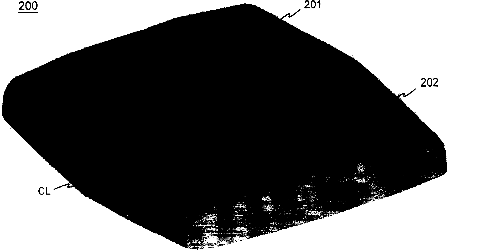
[0021] figure 2 An embodiment of the antenna blank of the present invention viewed from above is shown. In this description and claims, an antenna blank refers to a part including at least one part in the shape of an antenna element that is extruded from a basic blank. The monolithic antenna blank 200 consists of figure 2 The dotted line in the example shows a first half 201 and a second half 202 separated by a center line CL. The two halves have the same shape and structure, which are symmetrical to each other in the antenna blank. The symmetrical structure of the extruded part facilitates extrusion processing. The edges of the antenna blank 200 are arc-shaped so that the shape of the outer surfaces of the two halves matches the inner surface of the cover of the radio device in which the antenna is placed.

[0022] Fig. 3 shows an embodiment of the manufacturing steps of the antenna of the present invent...


PUM


Abstract

The invention relates to a method of manufacturing a structure suitable as an internal antenna in small radio devices, and an antenna element to which the method is applied. The antenna element comprises a radiating plane and additionally e.g. supportive elements, a feed conductor and short-circuit conductor as well as extensions to increase capacitance. The antenna element is fabricated by first extruding from a billet an antenna billet, and working the latter as required. The antenna billet may be symmetrical so that two antenna elements will be produced when it is cut in half. Advantageously the antenna element is fabricated so as to conform with the covering of the device in which it is placed. It may also be part of a covering of a device. The manufacturing costs of the antenna element are relatively low and the radio characteristics of the element are good. An antenna structure employing the element has got few separate parts and is mechanically firm and space-conserving. <IMAGE> <IMAGE>

Description

Technical field [0001] The present invention relates to a method of manufacturing a structure that can be used as a built-in antenna in a small radio device. In addition, the present invention relates to an antenna element made by this method. Background technique [0002] The manufacturing cost of general devices, especially mass-produced products, should be as low as possible. The fewer parts in the structure and the steps to make the parts, the lower the cost. In addition, in portable radio devices, the mechanical stability of the structure is very important. For example, in high-frequency antennas, even small mechanical changes can render the entire device unusable. The fewer the number of parts in the structure, the stronger the parts and the better the protection, the higher the stability and thus the reliability of the structure. Therefore, a small number of parts of a device helps reduce production costs and improve reliability. [0003] As far as antennas are concerned, ...

Claims


Application Information

Patent Timeline
Patent Type & Authority Patents(China)
IPC IPC(8): H01Q1/36H01Q1/27H01Q1/24H01Q9/04H01Q5/00H01Q5/371
CPCH01Q1/243H01Q9/0421H01Q9/0442H01Q5/371
Inventor M·波尔迪P·安纳马尔E·米科宁S·拉尔蒂凯宁
Owner PULSE FINLAND
Why Eureka
Try Eureka