
Wide bore rotary encoder
A rotary encoder and large-diameter technology, applied in the field of encoders, can solve problems such as errors, and achieve the effects of high precision, flexible application, and low cost
- Summary
- Abstract
- Description
- Claims
- Application Information
AI Technical Summary
Problems solved by technology
Method used
Image

Examples
Embodiment Construction
[0021] The present invention will be further described below in conjunction with the drawings and a specific embodiment, but the protection scope of the present invention should not be limited by this.
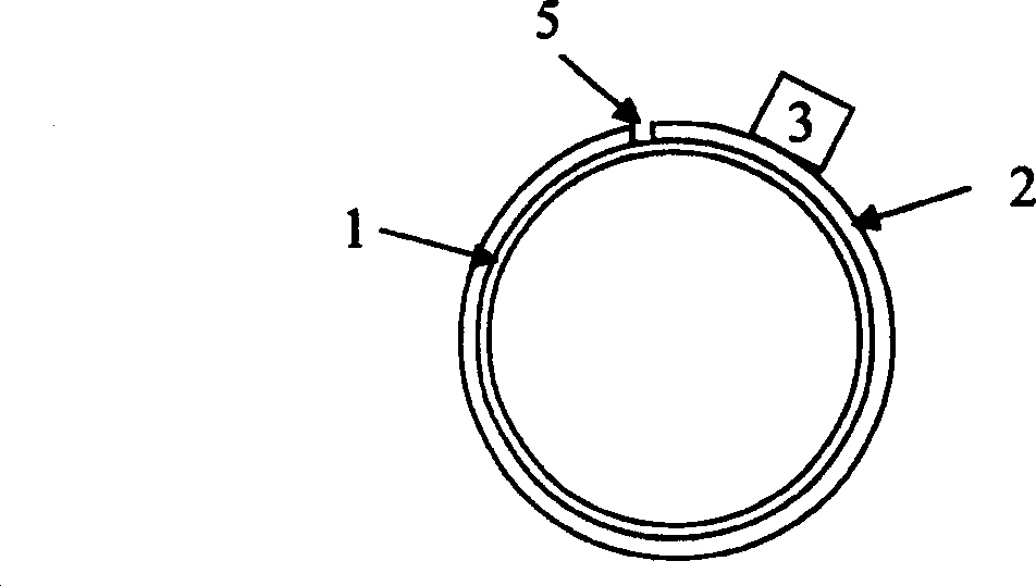
[0022] see first Figure 4 and Figure 5 , as can be seen from the figure, the large-diameter rotary encoder of the present invention includes a grating scale 2, a first reading head 3, a second reading head 4 and a zero mark 8, and is characterized in that the composition of the rotary encoder is: one and the to-be-measured Rotate the assembly ring 1 that the size of the parts matches, paste the grating scale 2 on the outer side of the assembly ring 1 greater than 180°, and install the zero mark 8 on the assembly ring at one end of the grating scale 2 1, the first reading head 3 and the second reading head 4 are relatively installed on the fixed part with respect to the assembly ring 1, and the output terminals of the first reading head 3 and the second reading head 4 pass t...
PUM
 Abstract
Description
Claims
Application Information