Communication terminal device and method of prevention of excessive interference

A communication terminal and signal technology, applied in wireless communication, selection device, multiplex communication, etc., can solve problems such as reducing transmission power, damaging user reliability of communication services, and disconnecting lines

Inactive Publication Date: 2001-07-18
PANASONIC CORP
View PDF3 Cites 4 Cited by
  • Summary
  • Abstract
  • Description
  • Claims
  • Application Information

AI Technical Summary

Problems solved by technology

At this time, in order not to cause interference to other mobile stations MS2 and MS3, the base station BS2 makes the mobile station MS1 ​​reduce its transmission power.
After the mobile station MS1 ​​reduces the transmission power, it cannot meet the power level required for the communication between the mobile station MS1 ​​and the base station BS1, and the line is cut off
[0009] After the line is cut off like this, the user must perform reconnection procedures, so the user's operation is very complicated, which damages the reliability of the user's communication service.

Method used


Image

  • Communication terminal device and method of prevention of excessive interference
  • Communication terminal device and method of prevention of excessive interference
  • Communication terminal device and method of prevention of excessive interference

Examples


Embodiment 1

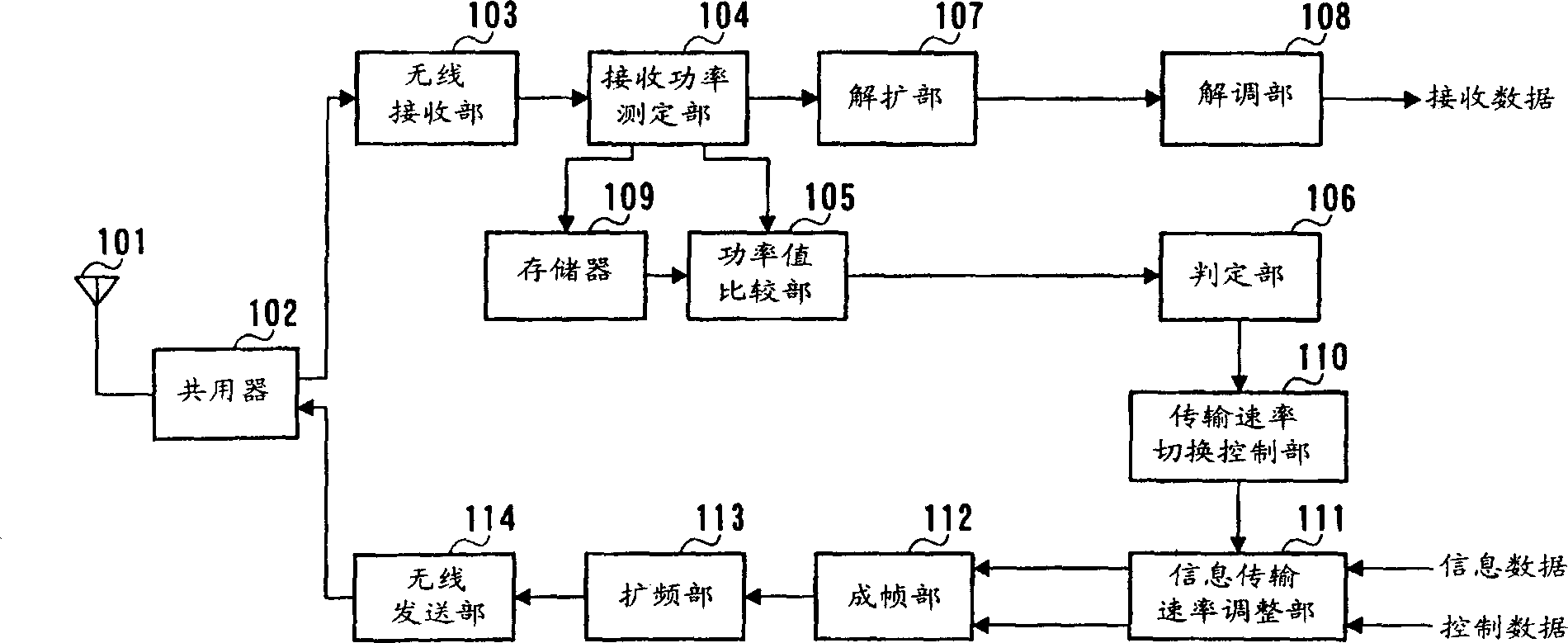
[0022] figure 2 It is a block diagram showing the configuration of a communication terminal device (mobile station) according to an embodiment of the present invention. Here, a communication terminal device in a CDMA digital radio communication system will be described.

[0023] A signal transmitted from a communication partner is received by a radio receiving unit 103 via an antenna 101 through a duplexer 102 . In the wireless receiving unit 103, various processing such as amplification (gain control), down-conversion, and A / D conversion are performed on the received signal. The A / D-converted signal is sent to the received power measurement unit 104, where the received power is measured. The measured received power value is sent to the power value comparison unit 105 and stored in the memory 109 .

[0024] In the power value comparing section 105 , the received power value sent from the received power measuring section 104 is compared with the received power value stored ...

Embodiment 2

[0047] Figure 5 It is a block diagram showing the structure of a communication terminal device (mobile station) according to Embodiment 2 of the present invention. Here, a communication terminal device in a CDMA digital radio communication system will be described.

[0048] A signal transmitted from a communication partner is received by a wireless receiving unit 403 via an antenna 401 through a duplexer 402 . In the wireless receiving unit 403, various processing such as amplification (gain control), down-conversion, and A / D conversion are performed on the received signal. The A / D-converted signal is sent to the received power measurement unit 404, where the received power is measured. The measured received power value is sent to the power value comparison unit 405 and stored in the memory 411 .

[0049] In the power value comparing section 405 , the received power value sent from the received power measuring section 404 is compared with the received power value stored in...


PUM


Abstract

The presence of a need for a handover operation is checked in the case of the rapid increase in the power values of received signals at a mobile communication terminal. Thereafter, if required, transmission rates of control data necessary for a handover operation, and of signals required for link maintenance are controlled not to be reduced, and a transmission rate of information data is controlled to rapidly be reduced. And if not needed, the transmission power is controlled to be reduced without changing the transmission rate.

Description

technical field [0001] The present invention relates to a communication terminal device such as a mobile station in a CDMA wireless communication system in which multiple access is performed by using spread spectrum in digital wireless communication, and a transmission power control method thereof. Background technique [0002] The CDMA (Code Division Multiple Access) method is one of the multiple access method technologies when a plurality of stations communicate simultaneously using the same frequency band in mobile communications such as car phones and mobile phones. As other technologies, there are known FDMA (Frequency Division Multiple Access) and TDMA (Time Division Multiple Access) methods. Compared with these technologies, the CDMA method can achieve higher frequency utilization. Efficiency, a way to accommodate more users. [0003] In the CDMA method, since a plurality of users share the same frequency band, a certain user's signal becomes an interference signal t...

Claims


Application Information

Patent Timeline
Patent Type & Authority Applications(China)
IPC IPC(8): H04B1/707H04B1/69H04B7/005H04B7/26H04J13/00H04L29/08H04W28/00H04W36/30H04W52/04H04W52/26H04W52/34H04W52/40
CPCH04W36/30H04W52/267Y02B60/50H04W52/40H04W52/34H04B7/26
Inventor 须增淳加藤修
Owner PANASONIC CORP
Why Eureka
Try Eureka