Data sending, receiving and transmission method, device and system
A technology for a data transmission system and a receiving end, applied in the field of communication, can solve the problem of not being able to use CPs of different lengths, and achieve the effect of avoiding inter-symbol interference
- Summary
- Abstract
- Description
- Claims
- Application Information
AI Technical Summary
Problems solved by technology
Method used
Image
Examples
Embodiment 1
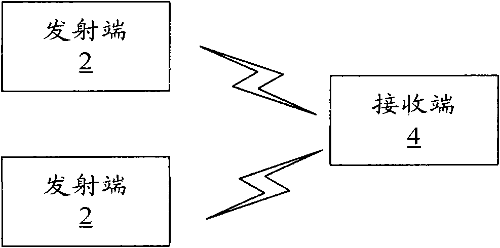
[0029] figure 1 is a schematic structural diagram of a data transmission system according to Embodiment 1 of the present invention, such as figure 1 As shown, the system includes: multiple transmitting terminals 2 and one receiving terminal 4 . Wherein, each of the multiple transmitting ends 2 is respectively located in one user equipment, and in the embodiment of the present invention, the cycle lengths used by each user equipment may be different.
[0030] Wherein, each transmitting end 2 is used to map the user data information and pilot bit information to be transmitted to the frequency domain resources allocated for the transmitting end (that is, the user equipment where the transmitting end is located) according to the length of the cyclic prefix used by it. Above, obtain the frequency domain signal, and convert the frequency domain signal into a time domain signal, add CP to the time domain signal and send it; wherein, the transmitter 2 using the preset length CP conve...
Embodiment 2
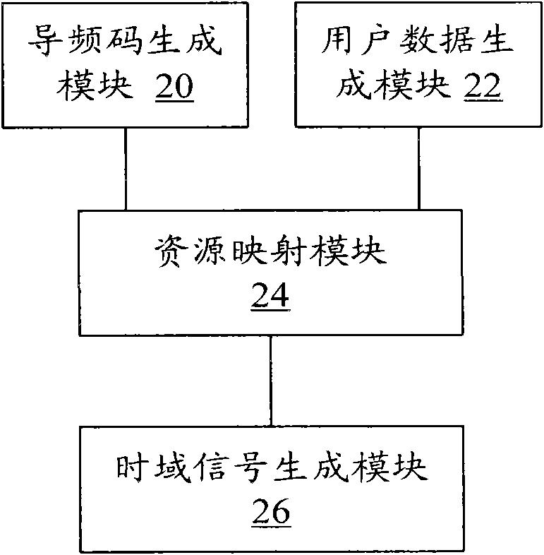
[0037] figure 2 is a schematic structural diagram of the transmitting end 2 according to Embodiment 2 of the present invention, the transmitting end is located in the user equipment, such as figure 2 As shown, in the embodiment of the present invention, the transmitting end 2 may include: a pilot code generation module 20 , a user data generation module 22 , a resource mapping module 24 and a time domain signal generation module 26 . Among them, the pilot code generating module 20 is used to generate pilot bit information according to the resource length allocated for the transmitting end (that is, the user equipment where the transmitting end is located), and input it into the resource mapping module, for example, assigning the transmitting end The length of the resource is 2M, if the CP length used by the transmitting end is a preset length (that is, the transmitting end is the first type of transmitting end), the length of the pilot bit information generated by the pilot ...
Embodiment 3
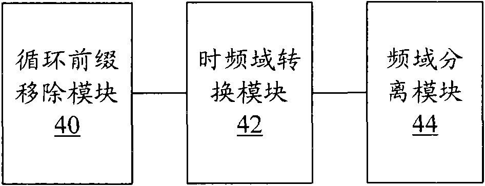
[0042] image 3 It is a schematic structural diagram of the receiving end 4 according to the third embodiment of the present invention, and the receiving end can be used in cooperation with the transmitting end 2 of the second embodiment. like image 3 As shown, the receiving end mainly includes: a cyclic prefix removal module 40 , a time-frequency domain conversion module 42 and a frequency domain separation module 44 . Among them, the cyclic prefix removal module 40 is used to receive time-domain signals sent by multiple transmitting ends 2 through wireless channels, and remove the CP of a preset length from the time-domain signals; the time-frequency domain conversion module 42 is used to convert The time-domain signal with the CP removed is converted to the frequency domain and input to the frequency-domain separation module 44; the frequency-domain separation module 44 is used to extract the received transmission end 2 transmissions according to the frequency domain reso...
PUM
 Abstract
Description
Claims
Application Information
 - R&D
- Intellectual Property
- Life Sciences
- Materials
- Tech Scout
- Unparalleled Data Quality
- Higher Quality Content
- 60% Fewer Hallucinations
Browse by: Latest US Patents, China's latest patents, Technical Efficacy Thesaurus, Application Domain, Technology Topic, Popular Technical Reports.
© 2025 PatSnap. All rights reserved.Legal|Privacy policy|Modern Slavery Act Transparency Statement|Sitemap|About US| Contact US: help@patsnap.com


