Method, device and system for data sending, receiving and transmitting

A technology for a data transmission system and a receiving end, applied in the field of communication, can solve the problem that CPs of different lengths cannot be used, and achieve the effect of avoiding inter-symbol interference

Active Publication Date: 2012-03-21
苏州医疗器械产业发展集团有限公司
View PDF4 Cites 8 Cited by
  • Summary
  • Abstract
  • Description
  • Claims
  • Application Information

AI Technical Summary

Problems solved by technology

[0005] The main purpose of the present invention is to provide a method for sending, receiving and transmitting data, a transmitting end, a receiving end and

Method used


Image

  • Method, device and system for data sending, receiving and transmitting
  • Method, device and system for data sending, receiving and transmitting
  • Method, device and system for data sending, receiving and transmitting

Examples


Embodiment 1

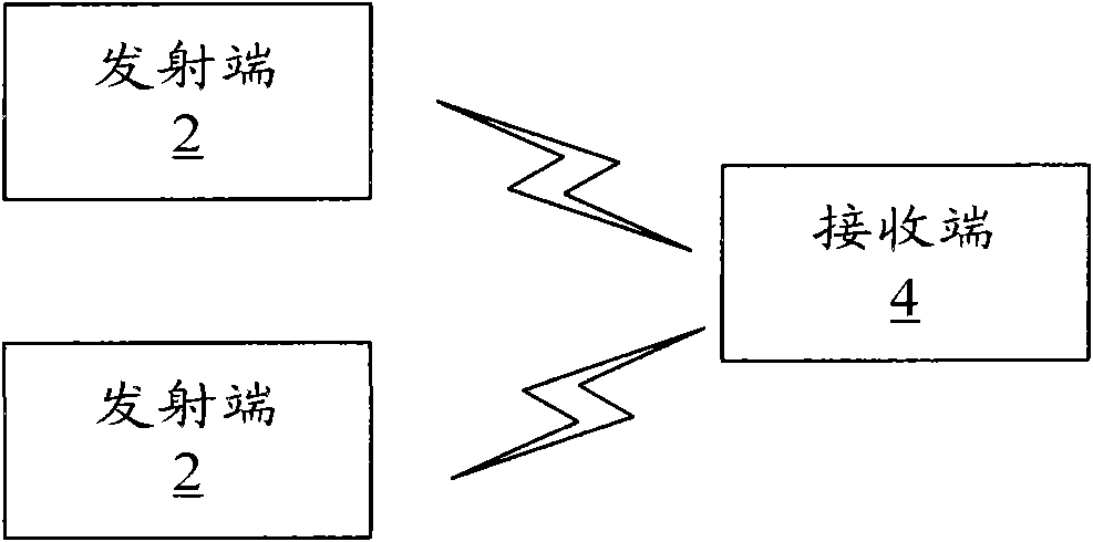
[0029] figure 1 is a schematic structural diagram of a data transmission system according to Embodiment 1 of the present invention, such as figure 1 As shown, the system includes: multiple transmitting terminals 2 and one receiving terminal 4 . Wherein, each of the multiple transmitting ends 2 is respectively located in one user equipment, and in the embodiment of the present invention, the cycle lengths used by each user equipment may be different.

[0030] Wherein, each transmitting end 2 is used to map the user data information and pilot bit information to be transmitted to the frequency domain resources allocated for the transmitting end (that is, the user equipment where the transmitting end is located) according to the length of the cyclic prefix used by it. Above, obtain the frequency domain signal, and convert the frequency domain signal into a time domain signal, add CP to the time domain signal and send it; wherein, the transmitter 2 using the preset length CP conve...

Embodiment 2

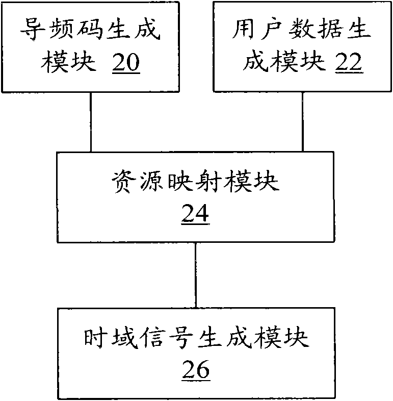
[0037] figure 2 is a schematic structural diagram of the transmitting end 2 according to Embodiment 2 of the present invention, the transmitting end is located in the user equipment, such as figure 2 As shown, in the embodiment of the present invention, the transmitting end 2 may include: a pilot code generation module 20 , a user data generation module 22 , a resource mapping module 24 and a time domain signal generation module 26 . Among them, the pilot code generating module 20 is used to generate pilot bit information according to the resource length allocated for the transmitting end (that is, the user equipment where the transmitting end is located), and input it into the resource mapping module, for example, assigning the transmitting end The length of the resource is 2M, if the CP length used by the transmitting end is a preset length (that is, the transmitting end is the first type of transmitting end), the length of the pilot bit information generated by the pilot ...

Embodiment 3

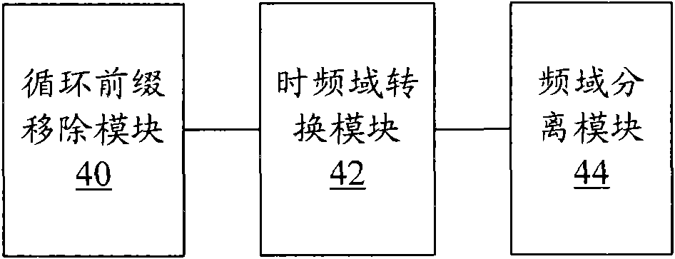
[0042] image 3 It is a schematic structural diagram of the receiving end 4 according to the third embodiment of the present invention, and the receiving end can be used in cooperation with the transmitting end 2 of the second embodiment. Such as image 3 As shown, the receiving end mainly includes: a cyclic prefix removal module 40 , a time-frequency domain conversion module 42 and a frequency domain separation module 44 . Among them, the cyclic prefix removal module 40 is used to receive time-domain signals sent by multiple transmitting ends 2 through wireless channels, and remove the CP of a preset length from the time-domain signals; the time-frequency domain conversion module 42 is used to convert The time-domain signal with the CP removed is converted to the frequency domain and input to the frequency-domain separation module 44; the frequency-domain separation module 44 is used to extract the received transmission end 2 transmissions according to the frequency domain r...


PUM

PropertyMeasurementUnit
Lengthaaaaaaaaaa

Abstract

The invention discloses a method, a device and a system for data sending, receiving and transmitting. The data sending method includes that all emitting ends map user data information and pilot bit information to be emitted on frequency domain resources distributing information for the emitting ends according to the length of a content provider (CP) the emitting ends use so as to obtain frequency domain signals. The emitting ends using the CP with prepared length continuously map the user data information and the pilot bit information on the frequency domain resources, and the emitting ends using the CP with unprepared length discontinuously map the user data information and the pilot bit information on the frequency domain resources. Signals of all the emitting ends are converted into time domain signals and sent after being added with the CP. The emitting ends using the CP with unprepared length remove partial time domain signals before adding the CP in the time domain signals, and the length and the position of the removed time domain signals correspond to the length of the CP the emitting ends use. The method, the device and the system can support users of different delay to coexist on the same subframe.

Description

technical field [0001] The present invention relates to the communication field, in particular, to a method for sending, receiving and transmitting data, a transmitting end, a receiving end and a data transmission system. Background technique [0002] The downlink of Long Term Evolution (referred to as LTE) adopts Orthogonal Frequency Division Multiplexing (referred to as OFDM) technology. OFDM has the characteristics of high spectrum utilization and anti-multipath interference. OFDM system It can effectively resist the influence brought by the wireless channel. The LTE uplink transmission scheme adopts a single-carrier frequency division multiple access system (SC-FDMA) with a cyclic prefix. , referred to as DFT) to obtain the frequency domain signal, and then insert zero symbols for spectrum shifting, and the shifted signal passes through IFFT (so, the SC-FDMA system is also called DFT-S-OFDM system), which can reduce the peak-average power of the transmitting terminal C...

Claims


Application Information

Patent Timeline
IPC IPC(8): H04L25/03H04L1/00
CPCH04L27/2607H04L5/0048H04L5/0037H04L5/0044
Inventor 李萍
Owner 苏州医疗器械产业发展集团有限公司
Why Eureka
Try Eureka