Redundancy and load balancing in a telecommunication unit and system

a telecommunications unit and load balancing technology, applied in data switching networks, frequency-division multiplexes, instruments, etc., can solve the problems of heavy network node structure, waste of resources, and high cost, and achieve the effect of balancing network load, high availability and transmission rate reduction

Active Publication Date: 2008-09-09
WSOU INVESTMENTS LLC
View PDF17 Cites 37 Cited by
  • Summary
  • Abstract
  • Description
  • Claims
  • Application Information

AI Technical Summary

Benefits of technology

[0008]The method, system and network element of the invention provide the advantage that 1:1 redundancy is not needed in the system and a pair can be defined for each cluster node even if there is an odd number of cluster nodes, for instance three. This way, when one cluster node malfunctions, only 33% of the PDP contexts need to be transferred to be served by another cluster node assuming that the load of the network element is divided between three cluster nodes.
[0009]In one embodiment of the invention, the network load is balanced in such a manner that when activating a PDP context, a logical node can be selected as the active node from the cluster node that has the least load. This embodiment also provides the advantage that one solution is provided for both network element load balancing and unit redundancy. This way, the system becomes resilient, i.e. has high availability and reliability. This is advantageous especially in a situation in which only a part of the sessions must have high availability. This embodiment is especially well suited for an environment comprising several all-IP-GGSN (Internet protocol) units based on solely packet-switched data transmission, in which resiliency and availability are required of the system. A further advantage of this embodiment is that it alleviates the problem related to load balancing based on IP-based packet transmission, i.e. the fact that the transmission rate can decrease significantly when the load increases.

Problems solved by technology

In circuit-switched connections, the capacity of the connection is, however, all the time reserved for a certain user, whereby resources are wasted and the user must also pay for this.
The problem with 1:1 redundancy is that it makes the structure of the network node heavy and expensive, if every processing unit is to be backed up.

Method used


Image

  • Redundancy and load balancing in a telecommunication unit and system
  • Redundancy and load balancing in a telecommunication unit and system
  • Redundancy and load balancing in a telecommunication unit and system

Examples


first embodiment

Implementation of the First Embodiment

[0033]The following describes, how the invention is implemented on the user plane.

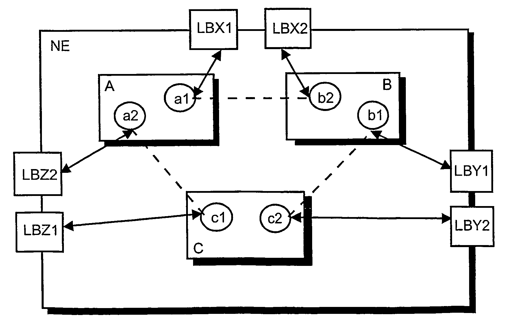
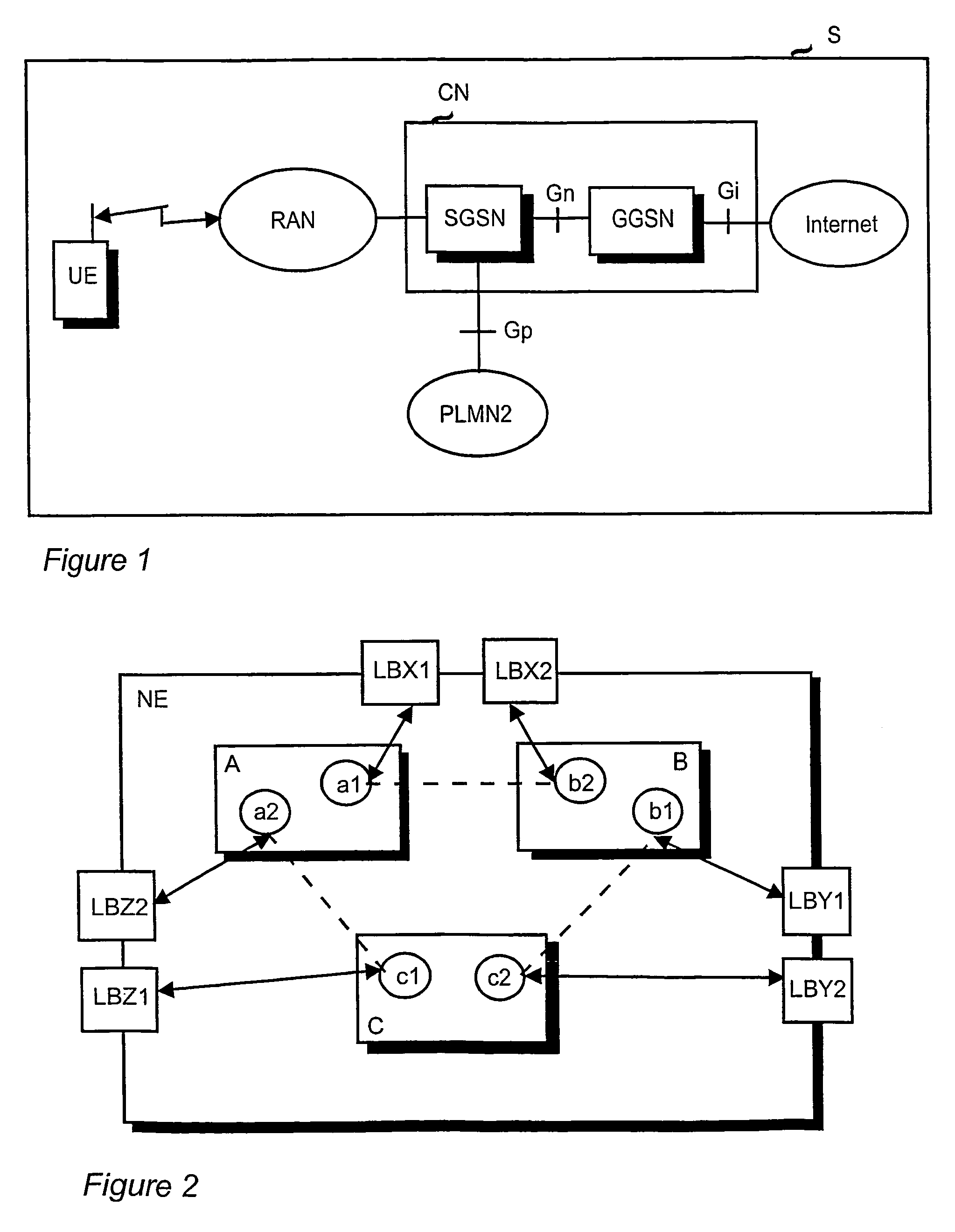
[0034]FIG. 2 shows a network element NE, which is for instance a GGSN node. The network element comprises two or more physical GTP-U processing units A, B, C, which are herein also called cluster nodes. The cluster nodes A, B, C are capable of serving PDP contexts. The cluster nodes are arranged in pairs such that each cluster node can form a pair with every other cluster node. For instance, if the number of available cluster nodes N=3, the number of possible pairs P=3. If N=4, then P=6. In the situation shown in FIG. 2, the number of cluster nodes N=3, and the possible cluster node pairs are then AB, BC and CA. In each pair, the first cluster node is a backup unit of the second cluster node.

[0035]According to the present invention, the cluster nodes contain logical nodes a1, a2, b1, b2, c1, c2, which are also called virtual cluster nodes or virtual nodes. The numb...

second embodiment

Implementation of the Second Embodiment

[0053]The following describes a combined user plane and control plane implementation of the invention.

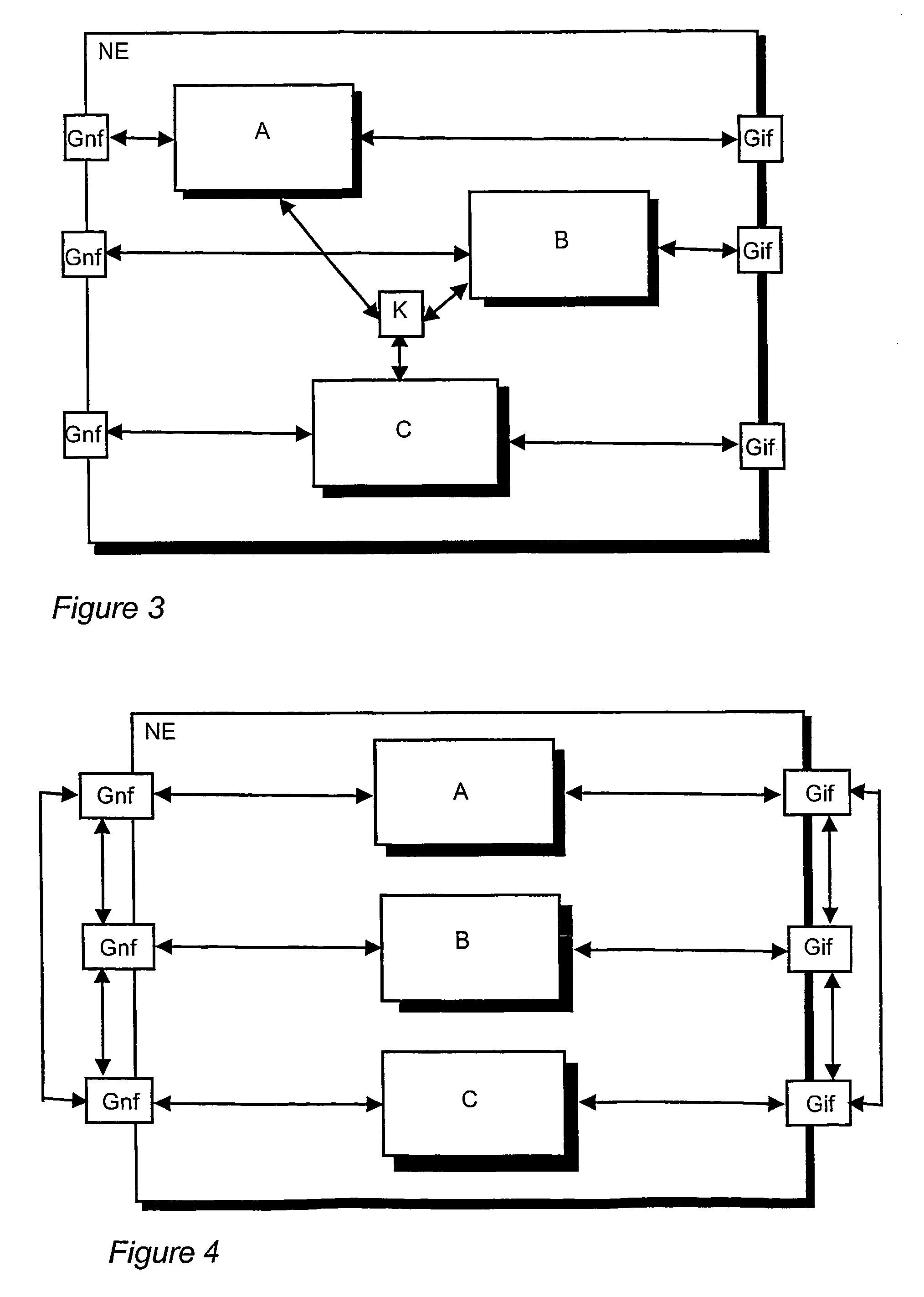
[0054]FIG. 5 shows a network element NE, which is for instance a GGSN node. The network element comprises two or more physical GTP-U processing units A, B, C, which are herein also called user plane cluster nodes, and two or more physical GTP-C processing units D, E, F which are herein also called control plane cluster nodes. The user plane and control plane cluster nodes A, B, C, D, E, F are capable of serving PDP contexts. According to the second embodiment of the invention, serving pairs are formed of the user plane and control plane cluster nodes such that a user plane cluster node and a control plane cluster node form a pair. In a serving pair, both of the nodes are active. Each user plane cluster node can form a pair with every control plane cluster node and vice versa. The serving pair has a backup pair on standby. Each backup pair can b...


PUM


Abstract

The invention relates to backing up a network element (NE) in a telecommunications system. The network element (NE) comprises at least two cluster nodes (A, B, C) that are redundancy units of each other. Each cluster node (A, B, C) contains virtual nodes (a1, a2, b1, b2, c1, c2). Pairs are formed of the virtual nodes (a1, a2, b1, b2, c1, c2) in such a manner that the first virtual node of the pair resides in the first cluster node and the second virtual node in the second cluster node. One of the virtual nodes in the pair is active and the other on standby. When a cluster node malfunctions, the virtual nodes of the pairs whose active virtual nodes reside in the faulty cluster node are interchanged by changing the standby virtual nodes to active and the active virtual nodes to standby.

Description

BACKGROUND OF THE INVENTION[0001]The invention relates to the redundancy of network elements and to load balancing in a telecommunications system, and especially to using parallel gateway nodes, such as GGSNs (Gateway GPRS support node) in a packet-switched mobile system. To provide a concrete example, the invention will be described in the context of a packet-switched mobile communication system.[0002]The continuous development of applications transmitted in mobile systems sets ever increasing demands on mobile networks. An efficient use of the radio network determining the capacity of the system is important to enable extensive traffic. Packet-switched connections are more efficient than circuit-switched connections in many applications. They are especially well suited for burst data transmission, such as for the use of the Internet. A high bit rate is then required to load a new page, but, on the other hand, data traffic is almost non-existent when the page is viewed. In circuit-...

Claims


Application Information

Patent Timeline
Patent Type & Authority Patents(United States)
IPC IPC(8): G06F11/22H04L45/24H04W24/04H04W28/08H04W40/32H04W40/34
CPCH04L45/00H04L45/22H04W40/34H04W28/08H04W40/32H04W24/04H04L45/645H04W28/088
Inventor AUTERINEN, OTSO
Owner WSOU INVESTMENTS LLC
Why Eureka
Try Eureka