Controlling a Transmission Rate of Packet Traffic

Active Publication Date: 2008-10-16
CISCO TECH INC
View PDF15 Cites 34 Cited by
  • Summary
  • Abstract
  • Description
  • Claims
  • Application Information

AI Technical Summary

Benefits of technology

[0004]In accordance with the present invention, disadvantages and problems associated with previo

Problems solved by technology

N-by-(N-1) switches, however, are typically expensive.
Moreover, it is sometimes difficult for N-by-(N-1) switches to accommodate additional processors because additional processors may require additional switch port interfaces.
Non-N-by-(N-1) switches, however, may experience head-of-line blocking problems.
Fo

Method used


Image

  • Controlling a Transmission Rate of Packet Traffic
  • Controlling a Transmission Rate of Packet Traffic
  • Controlling a Transmission Rate of Packet Traffic

Examples


Example

DETAILED DESCRIPTION OF THE DRAWINGS

[0014]Embodiments of the present invention and its advantages are best understood by referring to FIGS. 1 through 3 of the drawings, like numerals being used for like and corresponding parts of the various drawings.

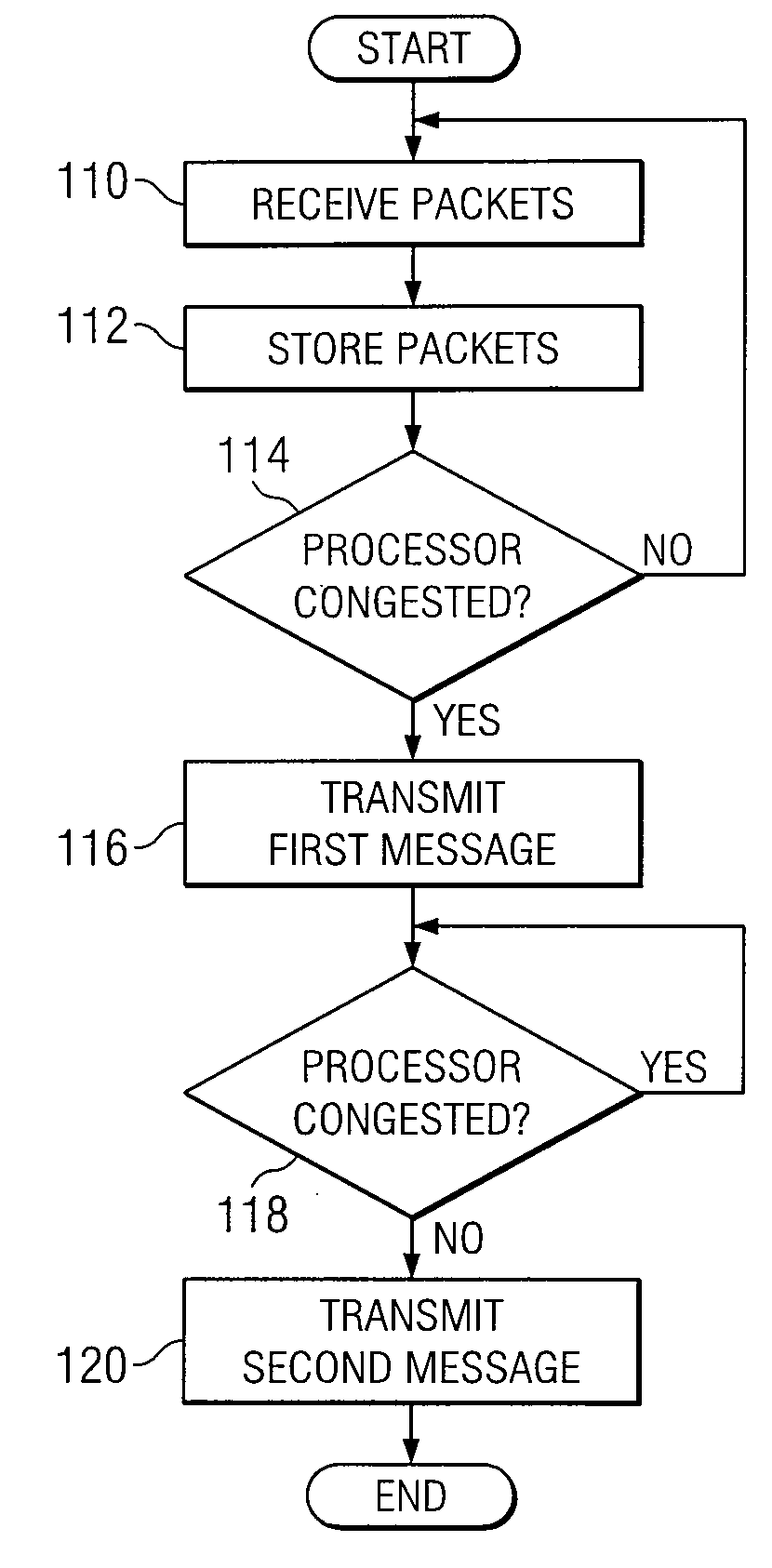
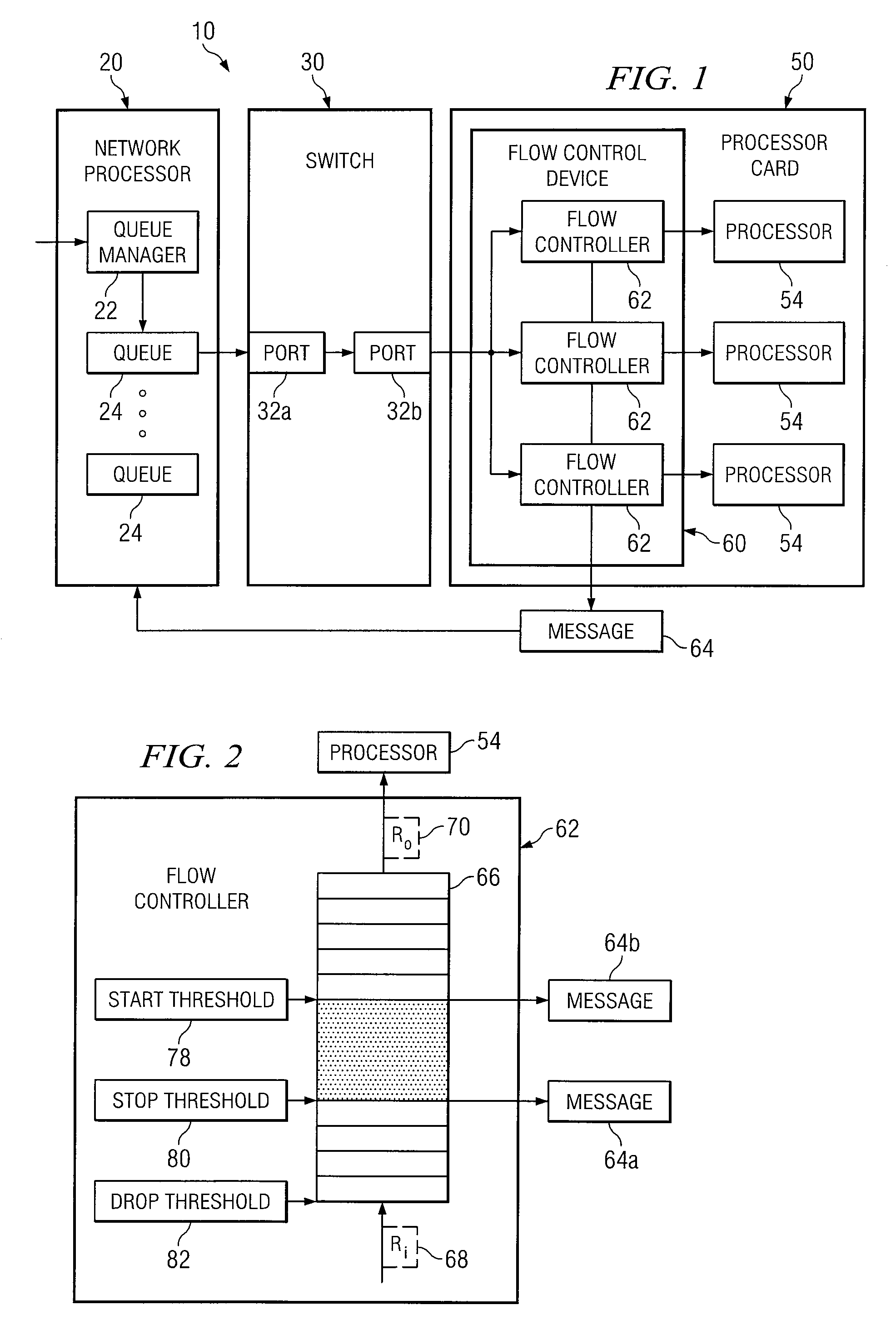
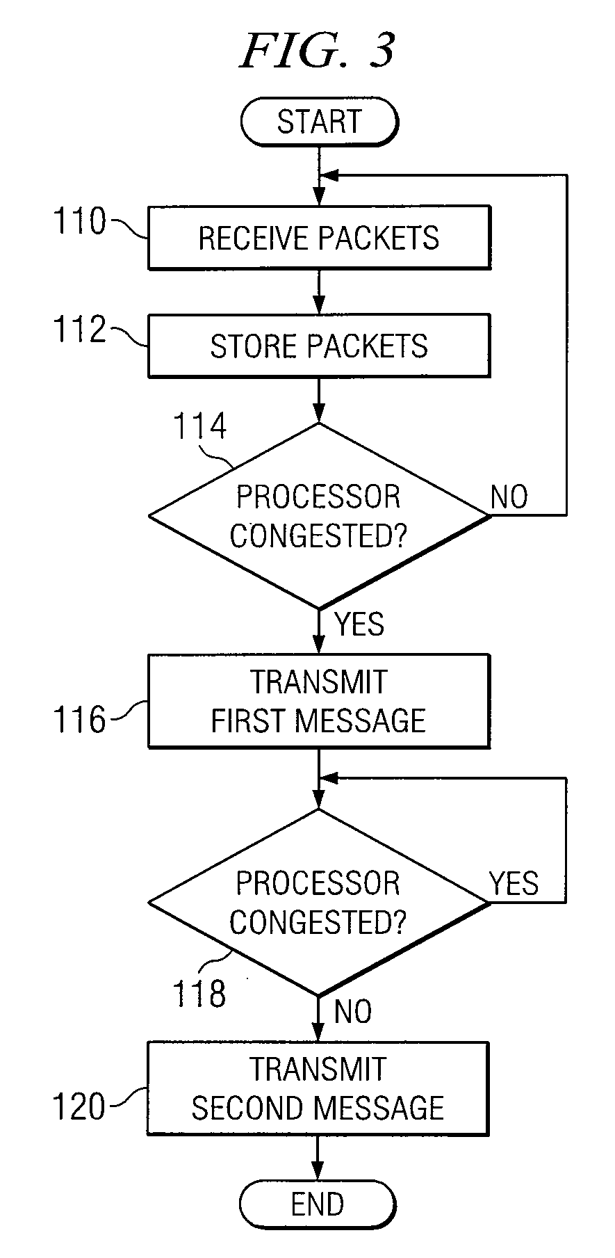
[0015]FIG. 1 illustrates one embodiment of a system 10 that includes a flow control device 60 that controls data traffic to processors 54. According to the embodiment, a network processor 20 transmits packet traffic to processors 54 at a transmission rate. Flow control device 60 uses one or more flow controllers 62 to determine if processors 54 are congested. In the embodiment, flow controllers 62 may determine that processors 54 are congested by monitoring an occupancy level of a buffer storing packet traffic for processors 54. If a flow controller 62 determines that processor 54 is congested, flow controller 62 may transmit a first message 64 indicating processor 54 is congested. In response, network processor 20 may decrease the tran...


PUM


Abstract

Controlling a transmission rate of packet traffic includes receiving packets from a network processor. The packets are stored in a buffer associated with a processor. If an occupancy level of the buffer is greater than a predetermined threshold, it is determined that the processor is congested. A message is transmitted to the network processor indicating the processor is congested.

Description

TECHNICAL FIELD[0001]This disclosure relates generally to the field of telecommunications and more specifically to controlling a transmission rate of packet traffic.BACKGROUND[0002]In distributed architectures, processors may communicate packets to one another through a switch. Some architectures use an N-by-(N-1) switch, which has a separate switch port interface for each processor. Thus, congestion of one interface does not affect other interfaces. N-by-(N-1) switches, however, are typically expensive. Moreover, it is sometimes difficult for N-by-(N-1) switches to accommodate additional processors because additional processors may require additional switch port interfaces.[0003]Other architectures use a non-N-by-(N-1) switch, where processors share a switch port interface. Non-N-by-(N-1) switches, however, may experience head-of-line blocking problems. For example, a processor may be congested and unable to accept more packets. Packets for the processor may block the switch port i...

Claims


Application Information

Patent Timeline
IPC IPC(8): H04L12/56
CPCH04L47/10H04L47/25H04L47/29H04L47/30H04L47/32
Inventor MONTALVO, RAFAEL MANTILLAGONZALEZ, JORGE MANUELMITCHELL, NATHAN ALLENMASTERSON, TIMOTHY F.HILLA, STEPHEN CHARLESSZYPULSKI, KAREN A.
Owner CISCO TECH INC
Why Eureka
Try Eureka