Front lamp for vehicle

A technology for headlights and vehicles, applied in vehicle lighting systems, headlights, vehicle components, etc., and can solve problems such as control

Inactive Publication Date: 2004-04-07
KOITO MFG CO LTD
View PDF2 Cites 10 Cited by
  • Summary
  • Abstract
  • Description
  • Claims
  • Application Information

AI Technical Summary

Problems solved by technology

[0010] That is, as described in "Patent Document 1", if only a plurality of identical lamp units are used, the pattern shape and light intensity distribution of the illumination pattern formed by the illumination of each lamp unit are the same, so there is the following problem , that is, it is impossible to finely control the illumination pattern of the obtained vehicle headlamp as its synthetic illumination pattern, so as to obtain the desired illumination intensity distribution

Method used


Image

  • Front lamp for vehicle
  • Front lamp for vehicle
  • Front lamp for vehicle

Examples


Embodiment Construction

[0039] Embodiments of the present invention will be described below using the drawings.

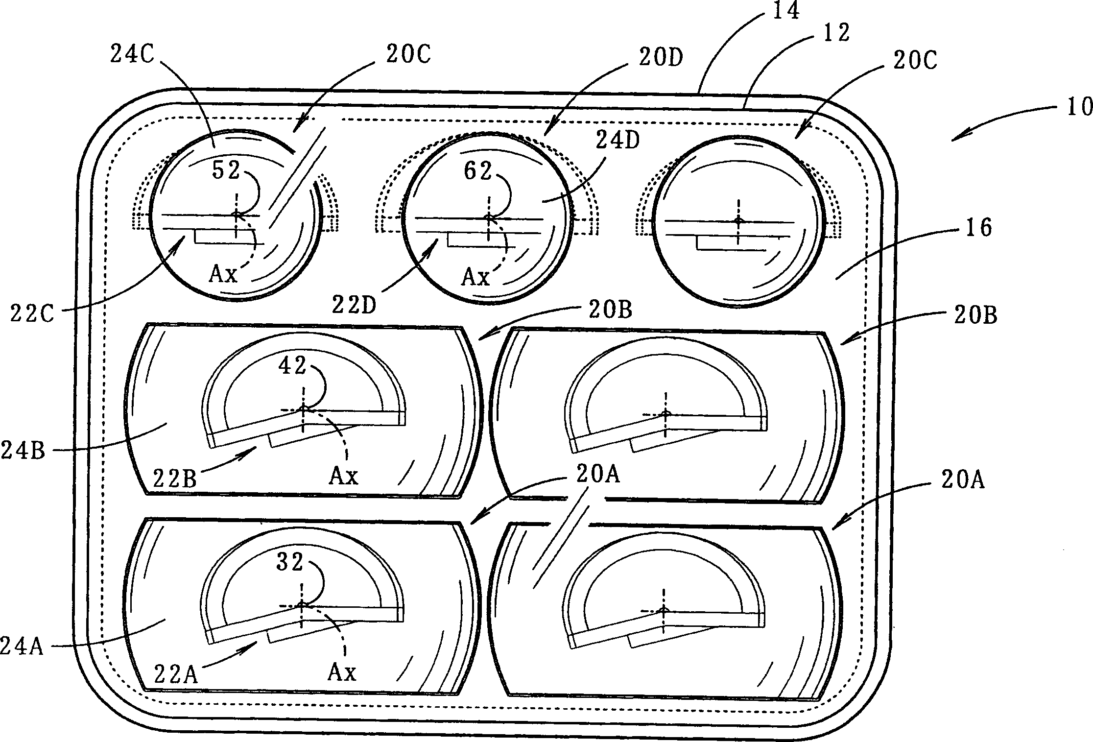
[0040] figure 1 It is a front view showing the vehicle headlamp 10 according to the embodiment of the present invention.

[0041] The vehicle headlamp 10 is a low beam headlamp. In an interior lamp formed by a transparent light-transmitting cover 12 and a lamp body 14, seven lamp units 20A, 20B, 20C, and 20D are covered in three stages above and below. containment. Among the plurality of lamp units in this embodiment, the lamp unit 20A constitutes a "first lamp unit", and the remaining lamp units 20B, 20C, and 20D constitute a "second lamp unit".

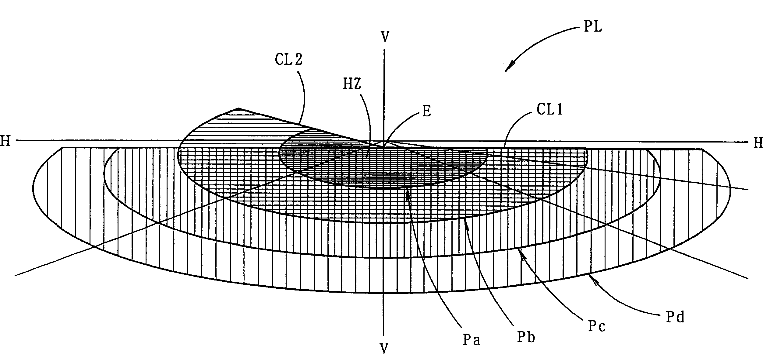
[0042] figure 2 A perspective view showing a low-beam illumination pattern PL formed on a virtual vertical screen arranged at a position 25 m in front of the lamp to show forward illumination by the vehicle headlamp 10 described above.

[0043] The illumination pattern PL for low beam is a left illumination pattern having horizontal and in...


PUM


Abstract

Headlight for vehicle. To allow a headlight for vehicle, which is configured so as to form a predetermined light distribution pattern, to control light intensity distribution of the light distribution pattern finely even if the headlight uses semiconductor light emitting elements as light sources. The headlight for vehicle comprises a plurality of lighting fixture units (20A, 20B, 20C, and 20D), which have light emitting diodes (32, 42, 52, and 62) as light sources respectively. The lighting fixture unit (20A) and the lighting fixture units (20B, 20C, and 20D) are used as a plurality of lighting fixture units, where the lighting fixture unit (20A) have a light emitting diode (32), on which a single light emitting chip (32a) is mounted, as a light source, and the lighting fixture units (20B, 20C, and 20D) have light emitting diodes (42, 52, and 62), on which light emitting chips (42a, 52a, and 62a) are mounted respectively, as light sources. Furthermore, a hot zone is formed by the radiation of the light from the lighting fixture unit (20A), and a diffusion region is formed by the radiation of the light from the lighting fixture units (20B, 20C, and 20D).

Description

technical field [0001] The present invention relates to a vehicle headlamp configured to form a predetermined illumination pattern. Background technique [0002] Conventional signal lamps for vehicles such as tail lamps often use light-emitting diodes as their light sources. For example, "Patent Document 1" describes a vehicle signal lamp in which a plurality of lamp units having light emitting diodes as light sources are arranged. [0003] Also, "Patent Document 2" describes a lamp that forms a desired illumination pattern in a vehicle headlamp by selectively lighting some of a plurality of light emitting diodes arranged in a matrix. [0004] 【Patent Document 1】 [0005] Japanese Patent Application Publication No. 2002-50214 [0006] 【Patent Document 2】 [0007] Japanese Patent Application Publication No. 2001-266620 [0008] In the lamp structure described in "Patent Document 2", the shape of the illumination pattern can be changed by separating the lighting and non-l...

Claims


Application Information

Patent Timeline
Patent Type & Authority Applications(China)
IPC IPC(8): F21S8/12B60Q1/04F21S8/10F21V13/00F21W101/10F21Y101/02
CPCF21S48/1163F21S48/1159F21Y2101/02B60Q1/04F21S48/1154F21Y2115/10F21S41/143F21S41/148F21S41/151F21S41/155F21S41/20F21S41/33F21W2102/00
Inventor 佐塚清石田裕之达川正士
Owner KOITO MFG CO LTD
Why Eureka
Try Eureka